Supersonic diagnostic appts.

An ultrasonic and bias power technology, applied in the directions of sonic diagnosis, infrasound diagnosis, diagnosis, etc., can solve the problems of large power consumption, short use time, and more heat generation, and achieve reduced power consumption, improved efficiency, and reduced noise. Effect

Inactive Publication Date: 2004-08-11
GE MEDICAL SYST GLOBAL TECH CO LLC
View PDF1 Cites 16 Cited by
  • Summary
  • Abstract
  • Description
  • Claims
  • Application Information

AI Technical Summary

Problems solved by technology

In such a structure, if the voltage applied from the transmitter power supply to the ultrasonic sensor is low, the voltage difference between the bias power supply and the transmitter power supply becomes large, resulting in large power consumption
[0009] This power consumption results in short operating times and high heat generation in portable ultrasound diagnostic devices powered by battery-operated ultrasonic transducers.

Method used


Image

  • Supersonic diagnostic appts.
  • Supersonic diagnostic appts.
  • Supersonic diagnostic appts.

Examples


Embodiment Construction

[0031] Now, an ultrasonic diagnostic apparatus according to an embodiment of the present invention will be described in detail with reference to the accompanying drawings.

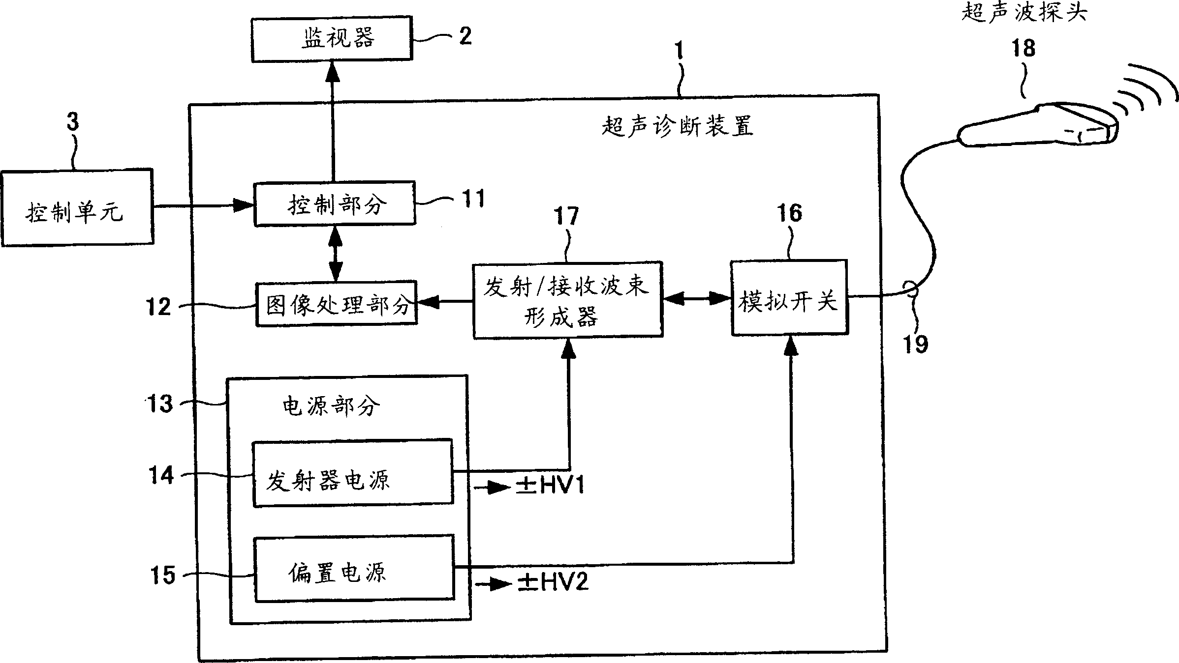
[0032] figure 1 is an explanatory schematic diagram for explaining the overall structure of the ultrasonic diagnostic apparatus according to the embodiment of the present invention. exist figure 1 , an ultrasonic diagnostic apparatus 1 is connected to a monitor 2 , a control unit 3 and an ultrasonic probe 18 . Monitor 2 can use any monitor, such as a CRT or LCD monitor. The control unit 3 can be a general-purpose input device, such as a keyboard or a mouse, or a dedicated control panel can be provided.

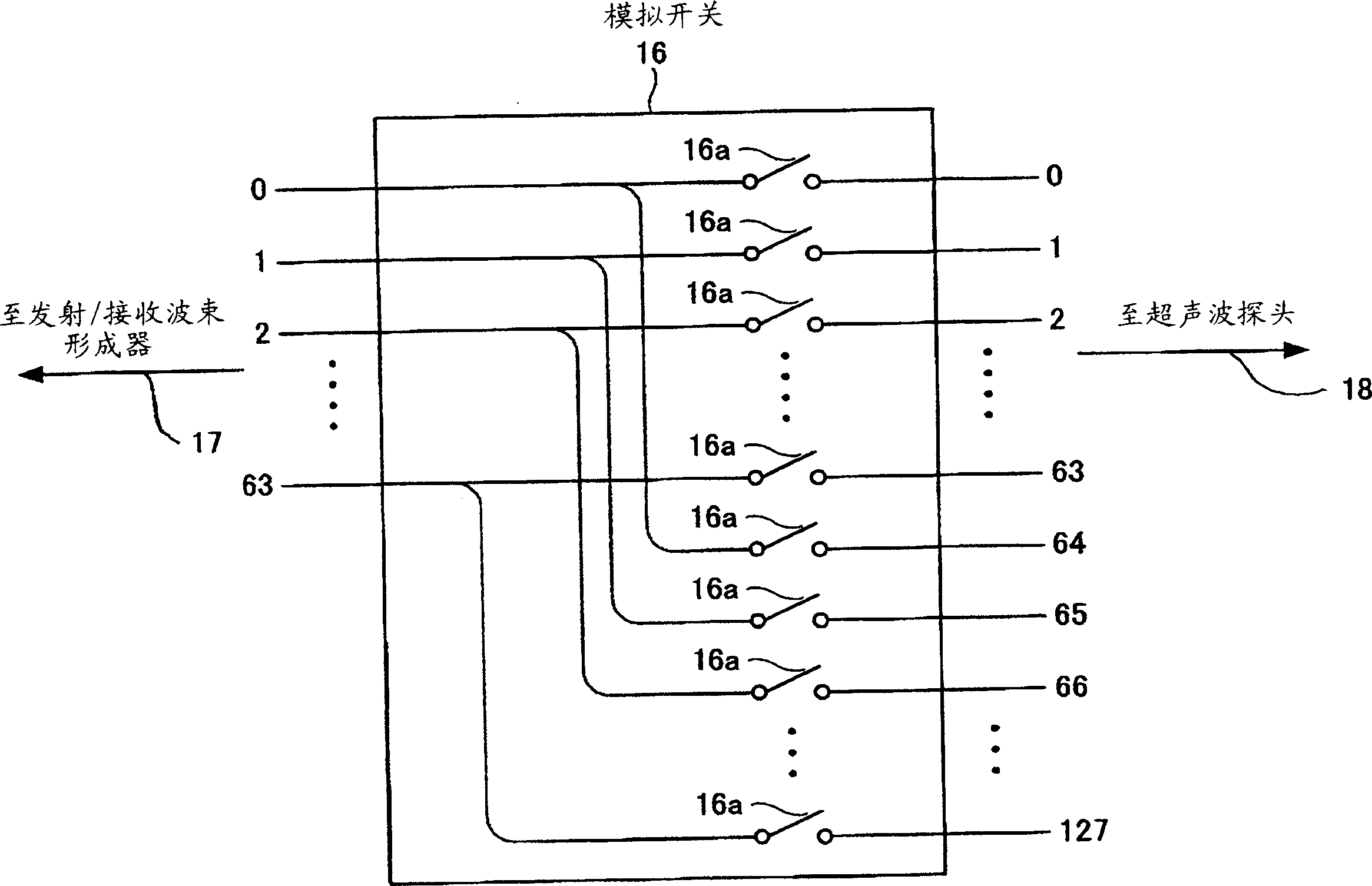
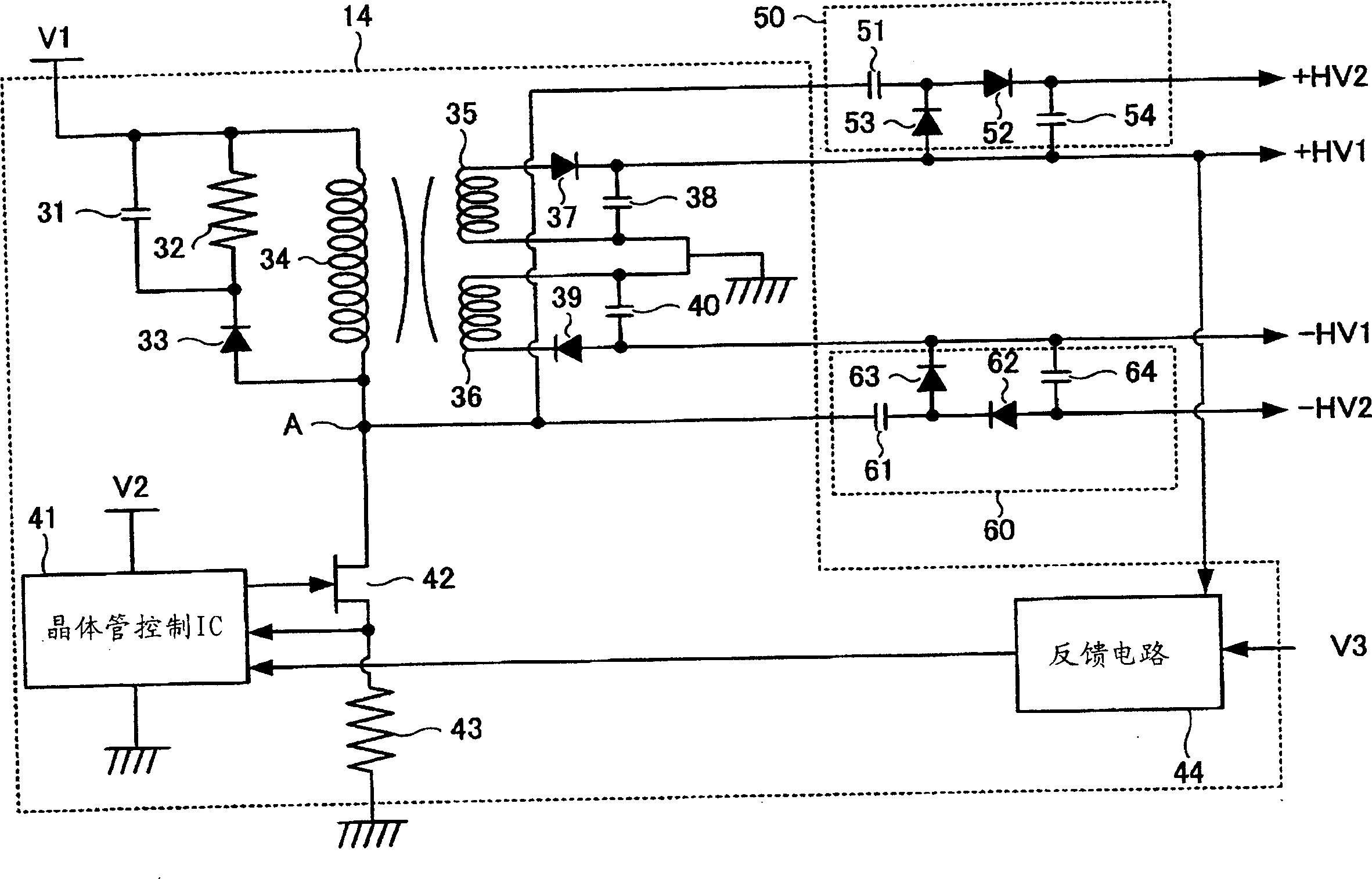
[0033] A control section 11 , an image processing section 12 , a power supply section 13 , an analog switch 16 and a transmission / reception beamformer 17 are also included in the ultrasonic diagnostic apparatus 1 . In addition, within the power supply section 13 there is a transmitter power supply 14 a...


PUM


Abstract

For the purpose of reducing the size and power consumption of a power source in an ultrasonic diagnostic apparatus, charge pump circuits (50 and 60) are connected to a transmitter power source (14). A regulator in the transmitter power source (14) drives the charge pump circuit (50) to generate a positive bias voltage +HV2 higher than a positive voltage +HV1 generated by the transmitter power source (14). The regulator in the transmitter power source (14) also drives the charge pump circuit (60) to generate a negative bias voltage -HV2 lower than a negative voltage -HV1 generated by the transmitter power source (14).

Description

technical field [0001] The invention relates to an ultrasonic diagnostic device, which is used for transmitting ultrasonic signals from an ultrasonic sensor to an object to be detected, and receiving the reflected waves of the ultrasonic signals for display, in particular to a small and low energy consumption ultrasonic diagnostic device. Background technique [0002] A commonly used conventional ultrasonic diagnosis is to image the inside of an object by applying ultrasonic waves to a region to be inspected inside the object with an adjacent ultrasonic probe, and to generate images of echo signals of reflected waves of the applied ultrasonic waves. Since ultrasonic waves are harmless to living bodies, ultrasonic diagnostic devices are particularly suitable for medical applications, and are used to detect foreign bodies in living bodies, determine the degree of damage, observe tumors or fetuses, and the like. [0003] In recent years, there has been a desire to reduce the si...

Claims


Application Information

Patent Timeline
Patent Type & Authority Applications(China)
IPC IPC(8): A61B8/00B06B1/02G01S7/524
CPCB06B2201/76G01S7/52019B06B1/0215G01S7/524A61B8/44A61B8/00
Inventor 雨宫慎一
Owner GE MEDICAL SYST GLOBAL TECH CO LLC
Why Eureka
Try Eureka