Axial sending-off powder type flame gun in supersonic speed using liquid fuel as energy sources

A technology of liquid fuel and axial powder feeding, which is applied in the direction of liquid injection devices, devices for coating liquid on the surface, injection devices, etc. Can not meet the technical requirements, the powder is easy to stick to the inner wall of the gun barrel, etc., to achieve the effect of prolonging the continuous operation time, easy linkage, and low porosity

Inactive Publication Date: 2004-08-11
王泰兴
View PDF0 Cites 11 Cited by
  • Summary
  • Abstract
  • Description
  • Claims
  • Application Information

AI Technical Summary

Problems solved by technology

[0002] At present, the structure of the known supersonic flame spray gun is that the gun barrel, Laval nozzle, combustion chamber, and tailstock are mechanically connected in sequence in the spray gun shell, and at the same time form a water cooling passage with the inner wall of the spray gun shell. The entrance and exit of this passage are arranged in the spray gun shell On the front and rear sections of the body, the front section of the spray gun shell is provided with a tangential powder feeding channel, and the tailstock is provided with a fuel delivery channel in the axial center. In the use of spray guns with this structure, it is found that the temperature of the combustion chamber is low due to the single tube delivery of fuel. Moreover, the temperature and pressure fields are not uniform, so it is only suitable for low melting point metal and alloy powders, especially the tangential powder feeding method has strict requirements on powder particle size and shape, the powder is easy to stick to the inner wall of the gun barrel, and the unmelted powder is The high-speed movement of the wall generates strong friction, which reduces the life of the barrel, low powder feeding efficiency, poor bonding force and deposition effect between the coating and the workpiece, and the coating density often cannot meet the technical requirements
In addition, the heat loss in the combustion chamber is large, which increases the processing cost. All the interfaces of the spray gun are rigidly connected to the external process pipe. Not only is the external pipe easy to break and break, but also the hand-held operation feels extremely cumbersome and consumes physical strength, which is not ideal.

Method used


Image

  • Axial sending-off powder type flame gun in supersonic speed using liquid fuel as energy sources
  • Axial sending-off powder type flame gun in supersonic speed using liquid fuel as energy sources
  • Axial sending-off powder type flame gun in supersonic speed using liquid fuel as energy sources

Examples


Embodiment Construction

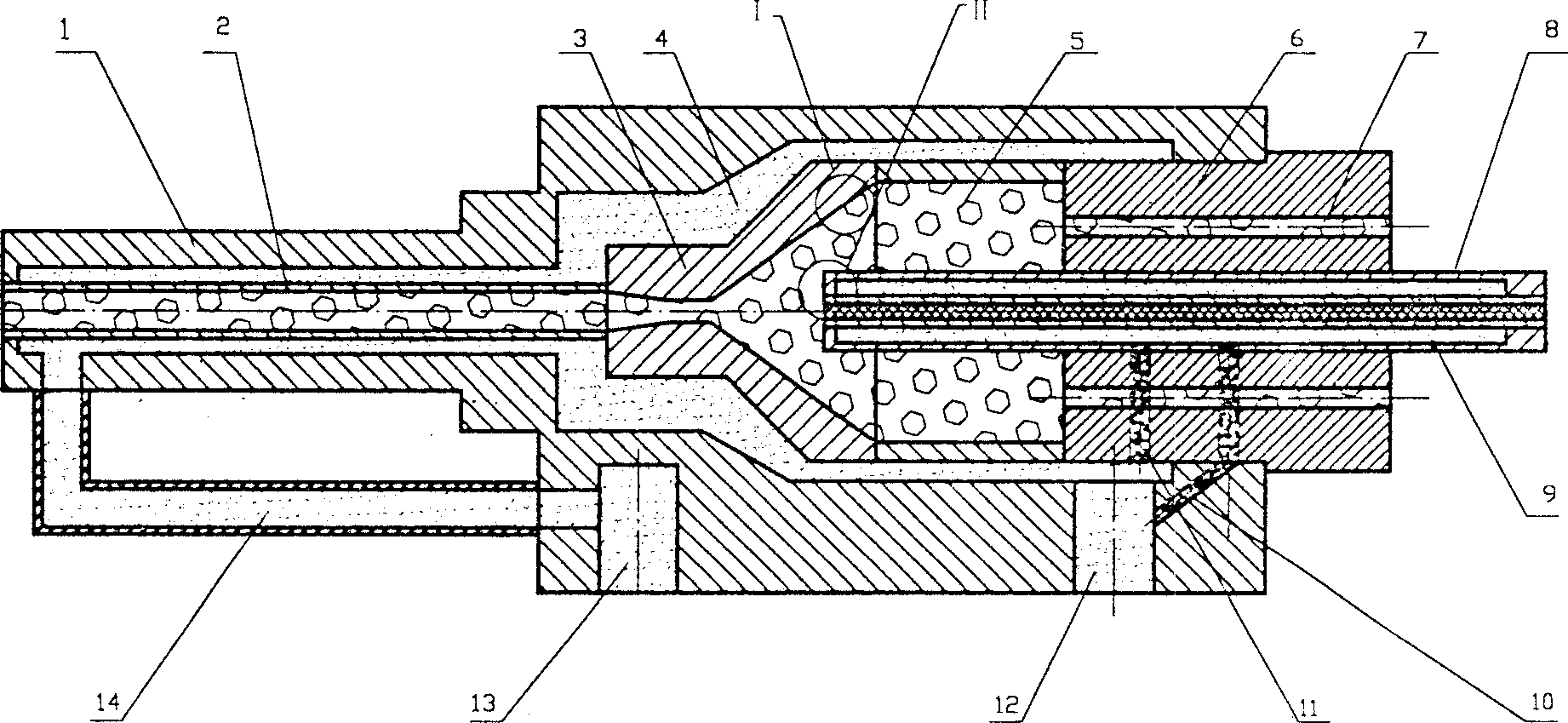
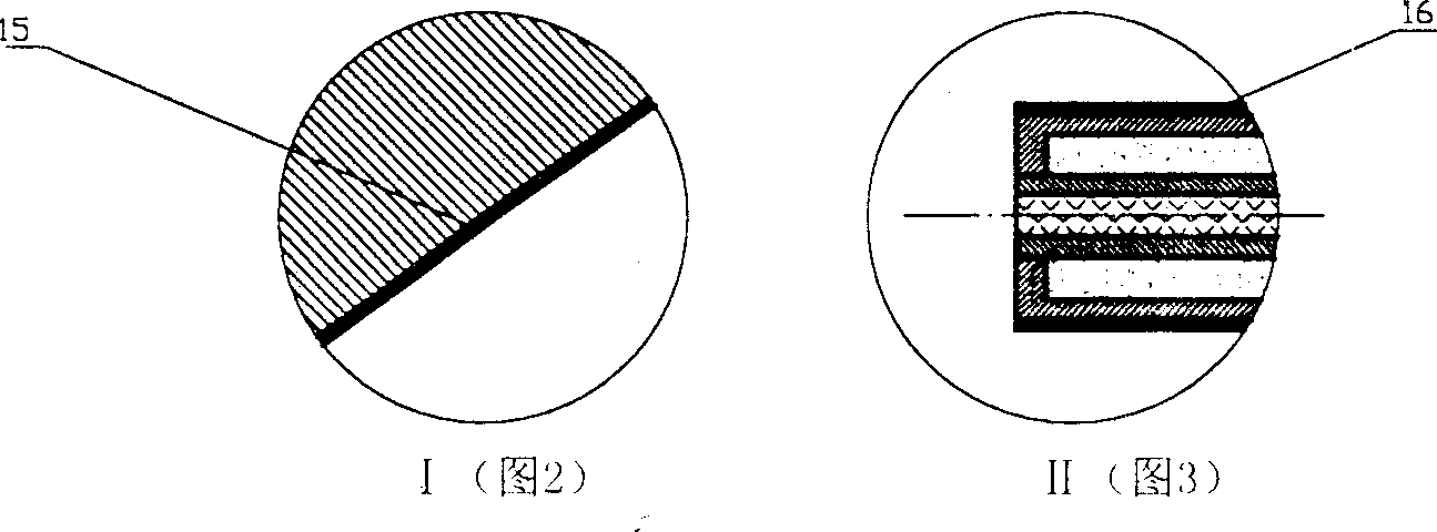
[0012] Depend on figure 1 -3 It can be seen that in the spray gun housing (1), there are gun barrel (2), Laval nozzle (3), combustion chamber (5) and tailstock (6), and are mechanically connected in turn, and the gun barrel (2 ), the Laval nozzle (3), the combustion chamber (5) and the tailstock (6) are formed with the inner surface of the spray gun housing (1) for cooling the gun barrel (2), the Laval nozzle (3), the combustion chamber (5) and the main water cooling passage (4) of the tailstock (6), one end of the passage is connected to the cooling water inlet (13) at the front of the spray gun housing (1) through the connecting pipe (14), and the other end is connected to the spray gun housing (1) The cooling water outlet (12) at the rear is connected. The internal diameter of the Laval nozzle (3) is divided into a necking section and a necking section. The inner wall of the combustion chamber (5) is provided with a heat-resistant coating (15), made of zirconia or alumina,...


PUM


Abstract

An axially feeding powder type supersonic flame spraying gun using liquid fuel as energy source is composed of a casing and the serially connected gum tube, convergent divergent nozzle, combustion chamber and tail unit. A main water cooling channel is formed between said casing and the serially connected units. In said tail unit, their is a water cooled powder feeding tube surrounded by 2-12 liquid fuel spraying tubes. Its advantages are high flowing speed of powder, fully smelting of powder, and high quality of coated layer.

Description

Technical field [0001] The invention relates to a spray gun for spraying metal surfaces, in particular to a supersonic flame spray gun with liquid fuel as energy source and axial DC powder feeding type. Background technique [0002] At present, the structure of the known supersonic flame spray gun is that the gun barrel, Laval nozzle, combustion chamber, and tailstock are mechanically connected in sequence in the spray gun shell, and at the same time form a water cooling passage with the inner wall of the spray gun shell. The entrance and exit of this passage are arranged in the spray gun shell On the front and rear sections of the body, the front section of the spray gun shell is provided with a tangential powder feeding channel, and the tailstock is provided with a fuel delivery channel in the axial center. In the use of spray guns with this structure, it is found that the temperature of the combustion chamber is low due to the single tube delivery of fuel. Moreover, the t...

Claims


Application Information

Patent Timeline
Patent Type & Authority Applications(China)
IPC IPC(8): B05B7/14B05B7/20B05C19/04
Inventor 王泰兴
Owner 王泰兴
Why Eureka
Try Eureka