Laminated heat exchanger

A heat exchanger and heat transfer tube technology, which is applied in the field of stacked heat exchangers, can solve the problems that the cooling and dehumidification of the exhaust air cannot be carried out smoothly, the temperature distribution difference of the exhaust air is increased, and the air heat exchange cannot be realized. The effect of uniform outlet surface temperature and discharge air temperature, improved cooling effect, and prevention of supercooled area and superheated area

Active Publication Date: 2004-08-11
HANON SYST
View PDF0 Cites 6 Cited by
  • Summary
  • Abstract
  • Description
  • Claims
  • Application Information

AI Technical Summary

Problems solved by technology

[0029] In addition, since a supercooled area and an overheated area are respectively generated in the heat transfer tube 10 flowing a large amount of refrigerant and the heat transfer tube 10 flowing a small amount of refrigerant, it is impossible to realize the air flow between the heat transfer tube 10 and the above-mentioned heat transfer tube 10. The uniform heat exchange, so the temperature distribution difference of the exhaust air increases
[0030] In addition, there is a possibility that, in the above-mentioned supercooled region, the surface of the evaporator 1 may freeze, etc., and the air conditioning system may become unstable. Rising humid air flows into the cabin, making occupants uncomfortable

Method used


Image

  • Laminated heat exchanger
  • Laminated heat exchanger
  • Laminated heat exchanger

Examples


Embodiment Construction

[0072] The present invention will be specifically described below with reference to the accompanying drawings.

[0073] Meanwhile, the description of the same parts as the related art is omitted.

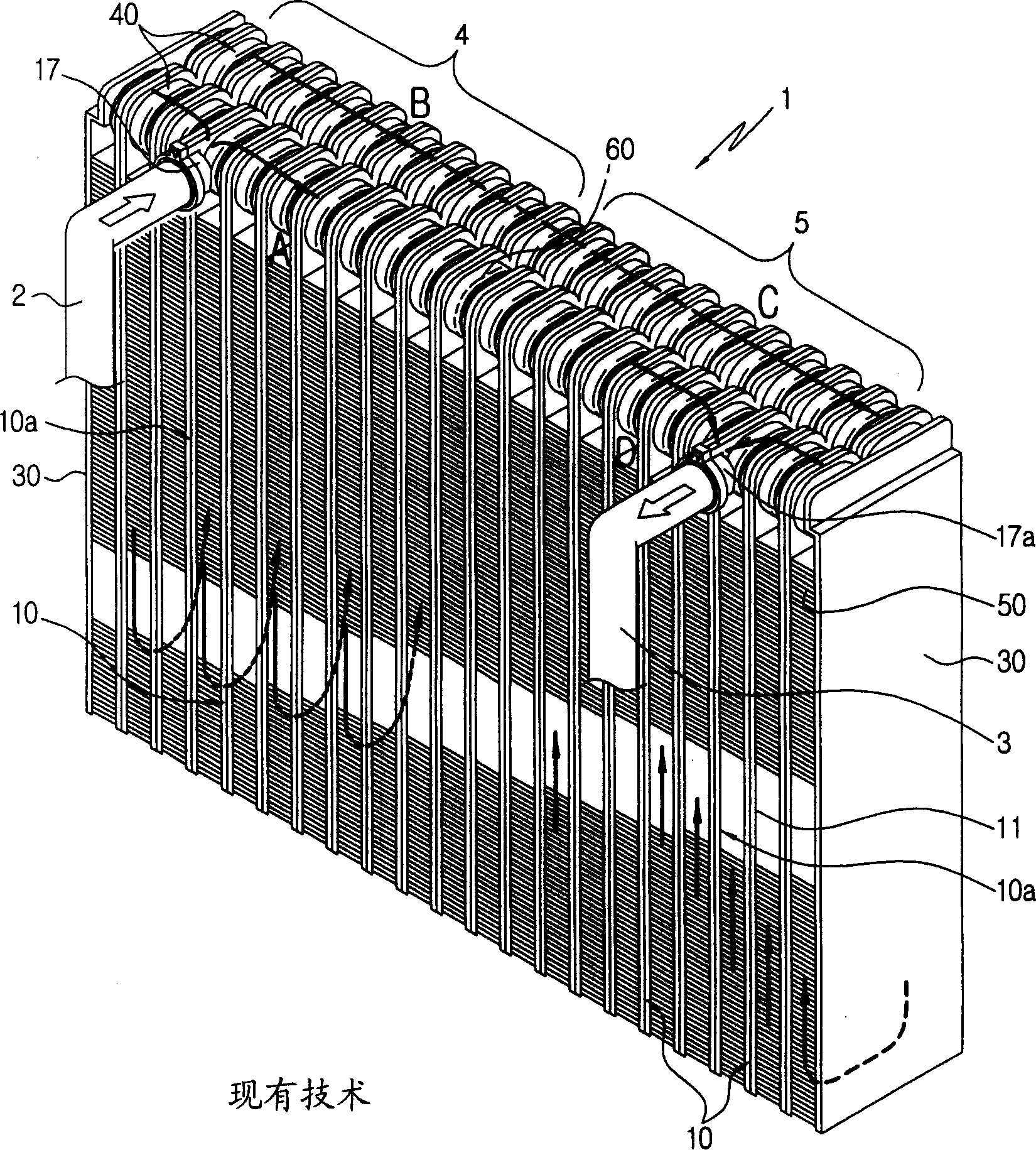
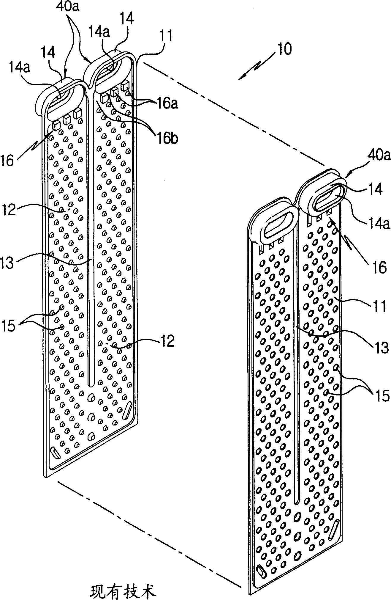
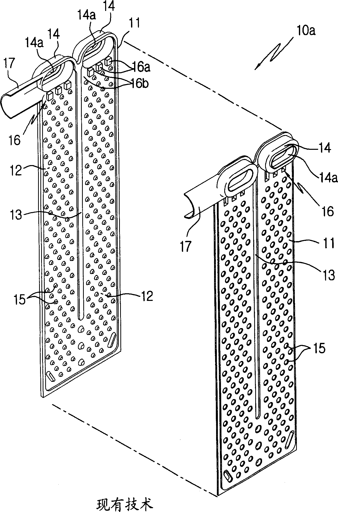
[0074] Figure 7 To represent the oblique view of the evaporator of the present invention, Figure 8 It is a perspective view showing the separated state of the heat transfer tube with manifold of the present invention, Figure 9 It is a diagram showing a state where the two outermost distribution channels of the refrigerant distribution part on the inlet and outlet sides are cut off by a bead in the heat transfer tube with a manifold of the present invention, Figure 10 It is a perspective view showing the separated state of the common heat transfer tube of the present invention, Figure 11 It is a diagram showing a state where the two outermost distribution channels of the refrigerant distribution part on the inlet and outlet sides are partitioned by beads in the general heat t...


PUM


Abstract

This invention relates to a laminated heat exchanger, more particularly, which is constructed to close some of distribution channels in refrigerant distributing sections of tubes to uniformly distribute refrigerant into the tubes thereby improving refrigerant flow distribution. The laminated heat exchanger comprises a number of laminated tubes, a refrigerant inlet pipe, a refrigerant outlet pipe, a number of heat radiator fins and at least one of the tubes includes a pair of tanks, a refrigerant flow section for connecting the tanks via a partitioning bead formed between the tanks, refrigerant distribution sections provided at inlet and outlet sides of the refrigerant flow section and each having a plurality of distribution channels partitioned by at least one bead, and channel-restricting means provided in each of the refrigerant distribution sections, for restricting two outermost ones of the distribution channels.

Description

technical field [0001] The present invention relates to a stacked heat exchanger, and more specifically, the present invention relates to a stacked heat exchanger in which a part of a distribution flow path formed in a refrigerant distribution portion of a heat transfer tube is blocked to distribute the refrigerant Evenly distributes inflow into each heat transfer tube. technical background [0002] "Heat exchanger" refers to a device that has a flow path for the refrigerant to flow inside and can exchange heat between the refrigerant and the outside air. It is used in various air-conditioning devices. Depending on the conditions of use, finned tubes (pin tubes) are used. Various forms such as serpentine type, drawn cup type, and parallel flow type. [0003] The evaporator 1 using a refrigerant as a heat exchange medium among the above heat exchangers will be described below as an example. [0004] Such as Figure 1 to Figure 6 As shown, the evaporator has: a heat transfer...

Claims


Application Information

Patent Timeline
Patent Type & Authority Applications(China)
IPC IPC(8): B60H1/32F25B39/02F28D1/03F28F3/08
CPCF28D1/0341F28D2021/0085F28F3/044
Inventor 黄善钟黄贵莲金德洙
Owner HANON SYST
Why Eureka
Try Eureka