Acoustic reflector for a baw resonator

A resonator and reflector technology, applied in the field of multiple layers of acoustic reflectors

Inactive Publication Date: 2004-08-18
AVAGO TECH INT SALES PTE LTD
View PDF1 Cites 12 Cited by
  • Summary
  • Abstract
  • Description
  • Claims
  • Application Information

AI Technical Summary

Problems solved by technology

If this tilt has even a small portion of the preferred direction, a vertical region can lead to the generation of shear waves in the piezoelectric layer

Method used


Image

  • Acoustic reflector for a baw resonator
  • Acoustic reflector for a baw resonator
  • Acoustic reflector for a baw resonator

Examples


Embodiment Construction

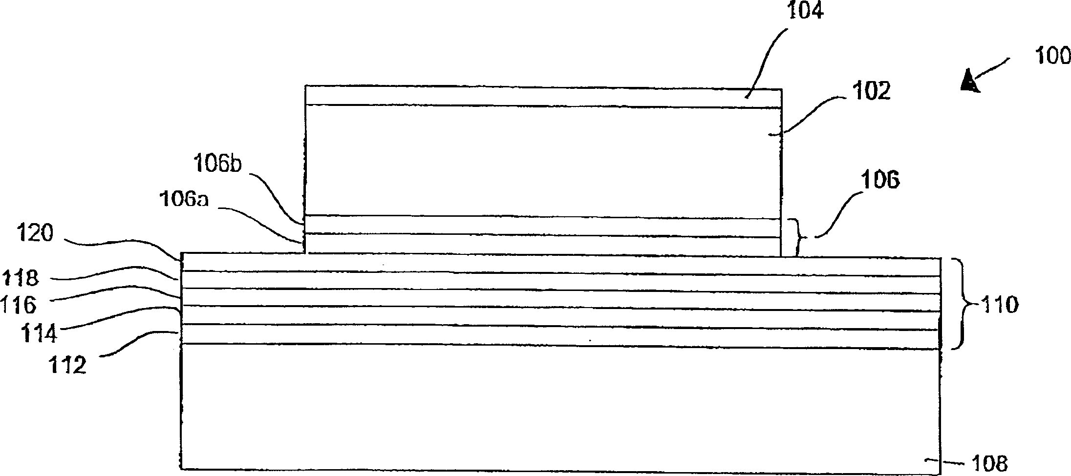
[0063] In the following description of the preferred embodiments, similar components are provided with similar or identical reference numerals in individual drawings.

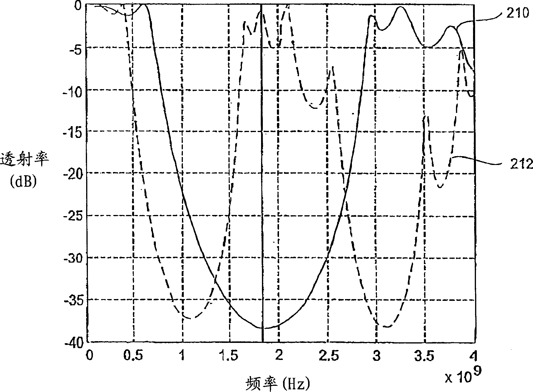
[0064] The present invention provides an acousto-acoustic mirror or acousto-acoustic reflector for a BAW resonator which leads to a significant improvement in the Q-factor. BAW resonators with acoustic reflectors of the present invention are particularly desirable in applications requiring a Q factor greater than 700, such as the antenna duplexers described above and other filter applications requiring low loss and high selectivity, such as US-CDMA or W-CDMA, use.

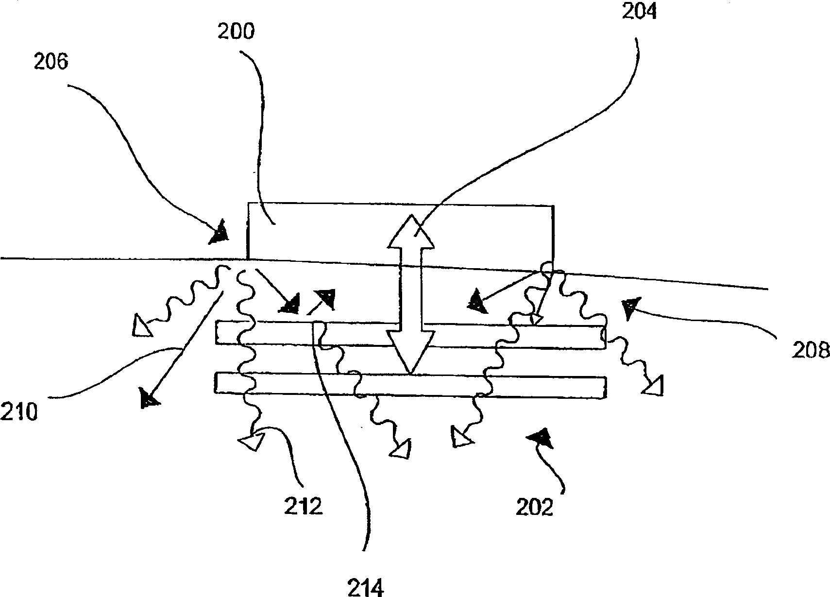
[0065] According to the invention, an improved acoustic reflector / acoustic mirror is provided which avoids loss of acoustic energy (sound dropout) in the vertical direction, ie in the direction in which individual layers of components are arranged above each other.

[0066] According to the first preferred embodiment of the present invention, the r...


PUM


Abstract

A BAW resonator includes a piezoelectric layer with a first surface and a second surface opposing the first surface, a first electrode disposed on the first surface of the piezoelectric layer, a second electrode disposed on the second surface of the piezoelectric layer, a substrate, and an acoustic reflector disposed between the substrate and the second electrode, the acoustic reflector comprising a plurality of layers from a material with high acoustic impedance and from a material with low acoustic impedance, wherein areas with layers with high acoustic impedance and areas with layers with low acoustic impedance are alternately adjacently disposed. A performance of the acoustic reflector is determined by its reflectivity for a longitudinal wave existing in the BAW resonator at the resonance frequency of the BAW resonator and by its reflectivity for a shear wave existing in the BAW resonator at the resonance frequency of the BAW resonator. The layers of the acoustic reflector and layers disposed between the acoustic reflector and the piezoelectric layer are selected, with reference to their number, material, and thickness, such that the transmissivity for the longitudinal wave and the transmissivity for the shear wave in the area of the resonance frequency is smaller than -10 dB.

Description

technical field [0001] The present invention relates to the sound reflector (acoustic mirror) that bulk wave resonator (block wave=BAW, bulk acoustic wave, referred to as BAW resonator below the bulk wave resonator) is used, especially here with respect to having improved BAW resonance Multiple layers of sound reflectors for devices. technical background [0002] The present invention preferably includes BAW filters for RF applications, and is herein particularly concerned with BAW filters in RF applications requiring good selectivity and steep transitions. In such filters, the most important parameters are the quality factor and the coupling coefficient of the BAW resonator. The coupling coefficient is defined by the frequencies at which successive resonances and parallel resonances occur. The coupling coefficient is a function of the electromechanical coupling of the piezoelectric layer of the BAW resonator to the thickness and type of material used in the overall arrang...

Claims


Application Information

Patent Timeline
Patent Type & Authority Applications(China)
IPC IPC(8): H03H9/56H03H9/17H03H9/58
CPCH03H9/175H03H9/56
Inventor S·马克斯泰恩纳G·法廷格R·阿格纳J·凯蒂拉
Owner AVAGO TECH INT SALES PTE LTD
Why Eureka
Try Eureka