Motor controller

A control device and motor technology, applied in motor control, motor generator control, AC motor control, etc., can solve the d, q axis DC component current control, the adverse effect of control performance, and the inability to separate AC component current and DC component current. and other problems to achieve the effect of rapid control

Inactive Publication Date: 2004-09-01
YASKAWA DENKI KK
View PDF2 Cites 3 Cited by
  • Summary
  • Abstract
  • Description
  • Claims
  • Application Information

AI Technical Summary

Problems solved by technology

In this way, when the high-pass filter 103 of the related art in the past detects the AC component of the q axis, it cannot separate the d, q axis AC component current and the DC component current.
[0008] 3. In the past related technologies, due to the compensation of the high-order harmonic current components in the power supply, the d-axis and q-axis DC component currents cannot be controlled within the desired value, so it cannot correspond to the position

Method used


Image

  • Motor controller
  • Motor controller
  • Motor controller

Examples


Embodiment 1

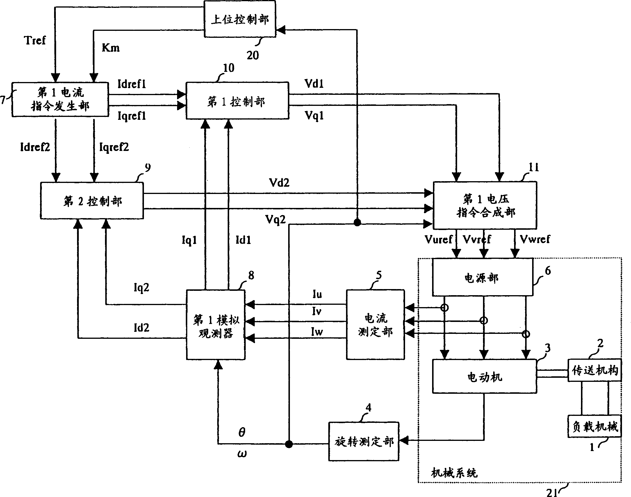
[0140] Below, while referring to figure 1 Next, Embodiment 1 of the present invention will be described.

[0141] figure 1 The illustrated embodiment 1 consists of the following parts:

[0142] It has a load machine 1, a transmission mechanism 2 that transmits power, a motor 3 that drives the load machine 1 through the transmission mechanism 2, and supplies drive according to a U-phase voltage command Vuref, a V-phase voltage command Vvref, and a W-phase voltage command Vwref. The mechanical system 21 of the power supply part 6 of the electric motor 3;

[0143] Provide a rotation measurement unit 4 that observes the state quantity of the mechanical system 21 and provides an actual response signal θ;

[0144] Observing the state quantities of the power supply unit 6, and providing the current measuring unit 5 for the actual U-phase current Iu, the actual V-phase current Iv and the actual W-phase current Iw;

[0145] A host control unit 20 that provides the torque command Tr...

Embodiment 2

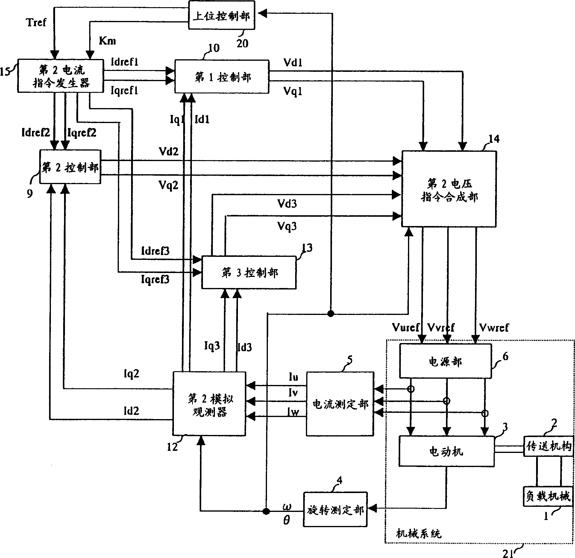
[0191] Below, refer to figure 2 Embodiment 2 of the present invention will be described.

[0192] figure 2 The illustrated embodiment 2 is composed of the following parts:

[0193] Observing the state quantity of the mechanical system 21 and providing the rotation measurement unit 4 with the actual response signal θ;

[0194] Observing the state quantities of the power supply unit 6, and providing the current measurement unit 5 with actual U-phase current Iu, actual V-phase current Iv and actual W-phase current Iw;

[0195] A host control unit 20 that provides the torque command Tref and the control mode command Km;

[0196] According to the torque command Tref and the control mode command Km, the 1d axis current command Idref, the 1q axis current command Iqref1, the 2d axis current command Idref2, the 2q axis current command Iqref2, the 3d axis current command Idref3 and the 3 The second current command generator 15 of the q-axis current command Iqref3;

[0197] Accord...

Embodiment 3

[0250] Below, refer to image 3 Embodiment 3 of the present invention will be described.

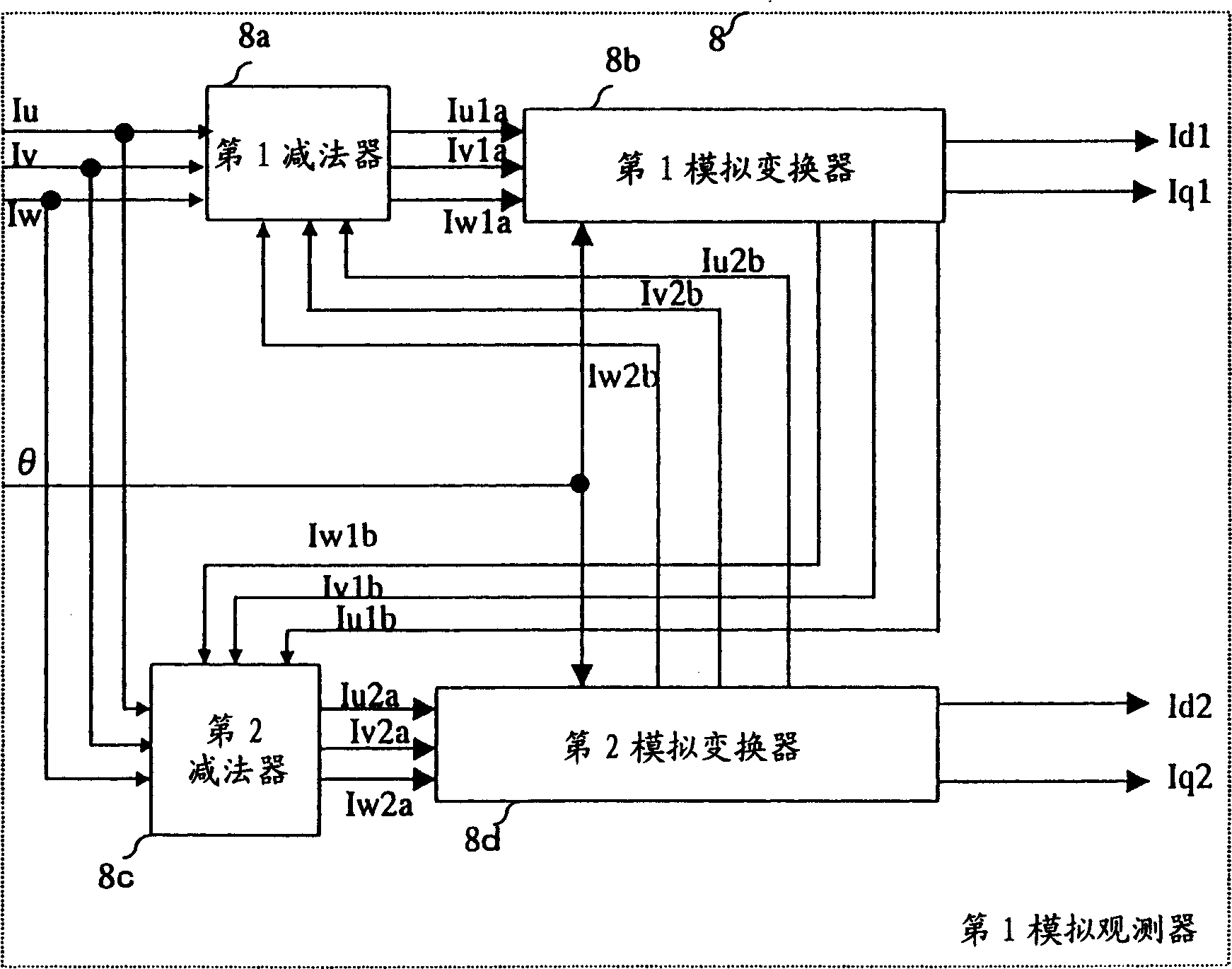
[0251] exist image 3 Among them, the first analog observer 8 of Embodiment 3 of the present invention is made up of the following parts:

[0252] Based on the actual U-phase current Iu, the actual V-phase current Iv, the actual W-phase current Iw, the U-phase 2b analog current Iu2b, the V-phase 2b analog current Iv2b, and the W-phase 2b analog current Iw2b, providing The first subtractor 8a of the U-phase 1a analog current Iu1a, the V-phase 1a analog current Iv1a and the W-phase 1a analog current Iw1a;

[0253] Based on the actual U-phase current Iu, the actual V-phase current Iv, the actual W-phase current Iw, the U-phase 1b-th analog current Iu1b, the V-phase 1b-th analog current Iv1b, and the W-phase 1b-th analog current Iw1b, providing The second subtractor 8c of the U-phase 2a analog current Iu2a, the V-phase 2a analog current Iv2a and the W-phase 2a analog current Iw2a;

[025...


PUM


Abstract

A motor controller has both a basic-frequency current component and a harmonic current component at the same time. A prior art does not allow the simultaneous cancellation of torque ripples generated in a motor because the harmonic current components (6f, 24f) cannot be compensated at the same time. The motor controller is constituted of a rotation measuring section (4), a current measuring section (5), a high-order control section (20), a second current command generator (15), second simulation observer (12), first control section (10), second control section (9), third control section (13), and second voltage command synthesis section (14). The second voltage command synthesis section (14) is constituted of three position converters, three reverse coordinate converters, and an adder.

Description

technical field [0001] The present invention relates to a motor control device that supplies an appropriate voltage to a motor (DC motor, induction motor, synchronous motor, linear motor, etc.) that drives a load machine such as a table of a machine tool or an arm of a robot using a semiconductor power conversion device. Background technique [0002] As a conventional related art, there is an active filter for electric power disclosed in JP-A-8-80052 (JP-A-6-210313). FIG. 10 shows a conventional related art. The power active filter shown in Fig. 10 is composed of three-phase AC power supply 113 and L load 114, active filter 112, subtractor 109, current control 110, PWM control 111, higher harmonic current detection circuit 2A, The kth harmonic current detection circuit 2B and an adder 108 for adding the outputs of the harmonic current detection circuit 2A and the harmonic current detection circuit 2B are configured. Further, the harmonic current detection circuit 2A is com...

Claims


Application Information

Patent Timeline
IPC IPC(8): H02P21/00H02P21/05H02P21/22H02P23/04H02P25/098H02P27/04H02P27/08H02P29/00H02P29/40H02P29/50
CPCH02P6/08H02P6/10
Inventor 郭双晖本田英己小黑龙一
Owner YASKAWA DENKI KK
Why Eureka
Try Eureka