Charging power generator set

A generator set and generator technology, applied in the direction of electric components, windings, electrical components, etc., can solve problems such as low efficiency, heavy weight, and large volume

Inactive Publication Date: 2004-09-08
CHINESE INTERNATIONAL SCIENCE & TECHNOLOGY PROMOTION ASSOC
View PDF0 Cites 0 Cited by
  • Summary
  • Abstract
  • Description
  • Claims
  • Application Information

AI Technical Summary

Problems solved by technology

The motor itself adopts a conventional structure, which is large i...

Method used


Image

  • Charging power generator set
  • Charging power generator set
  • Charging power generator set

Examples


Embodiment Construction

[0011] Embodiments are described in detail below in conjunction with the accompanying drawings.

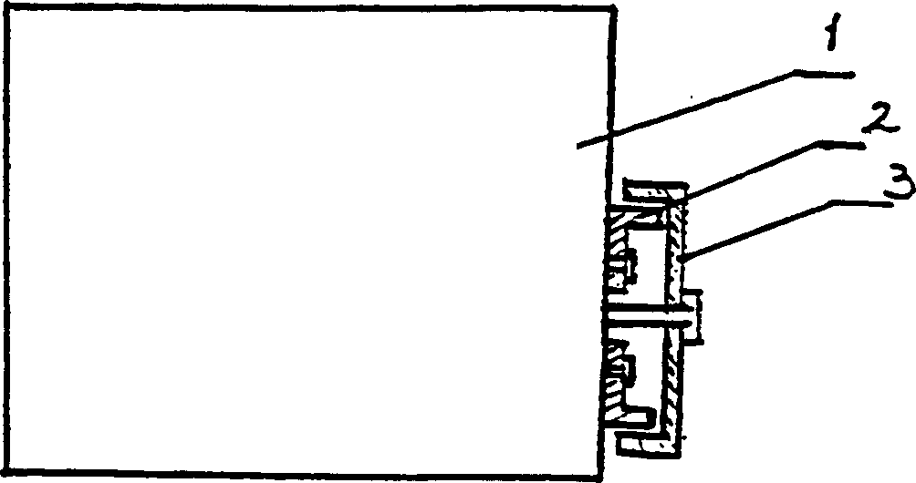
[0012] Fig. 1 is a schematic diagram of the connection between the generator set and the power machine of the present invention. The generator set includes a power machine 1, a generator rotor 3 directly connected to the power machine shaft, and a generator stator 2 fixed on the power machine casing. That is, the generator set of the present invention is a machine in which the power machine and the generator are integrated. The power machine is a gasoline engine or a diesel engine.

[0013] The power of the generator in this example is 2.7KW, 56 poles, 112 slots, and the generator speed is 3000rpm. It is an external rotor generator, but it is not necessary.

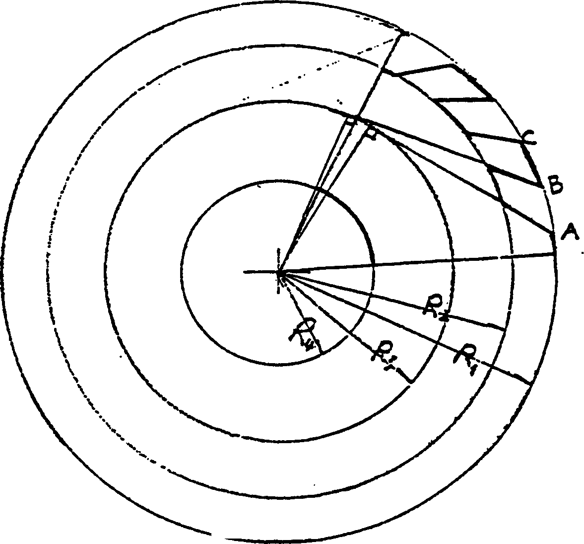
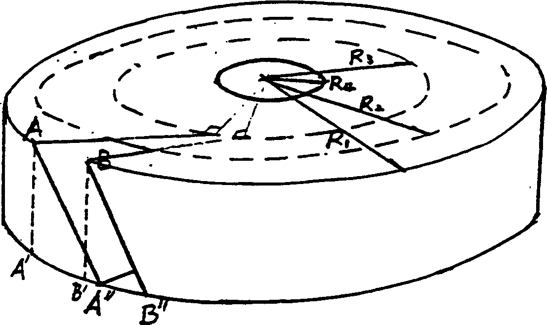
[0014] The stator 2 is a cylinder made of silicon steel sheets, and a plurality of grooves are arranged in its outer circumference. Figure 2 is a schematic diagram of the structure formed by the grooves, R 1 is the outer r...


PUM


Abstract

The charging power set is a permanent magnetic outer rotor type one with peripheral permanent magnets in interval of 0.5-0.8 time the width; single phase winding embedded inside the stator groove; stator groove in special shape and size; stator shaft twisted relatively to the axis with the total twisting amount being 12 times the slot width; and stator winding divided into several groups. Each of the windings has the output connected via reactor to AC side of rectifier, and the DC outputs of the rectifiers are connected serially and parallelly to combine varying DC output voltage for charging different load. The power set has high power-to-volume ratio, small volume, light weight, high conversion efficiency and good charging characteristic. The power set is used as DC power supply for constant current charging and fast charging and may be also used as other DC power supply.

Description

technical field [0001] The invention relates to a permanent magnet generator set matched with a diesel or gasoline power engine, more specifically, a charging generator set driven by a diesel or gasoline power engine. Background technique [0002] There is no specially designed genset for charging at present, and the gensets driven by the existing diesel engine and gasoline engine are used as charging gensets, but the genset is charged through another rectification system. The composition of its generator and power machine is basically the amalgamation of two independent bodies. The motor itself adopts a conventional structure, which is large in size, heavy in weight and low in efficiency, and the charger is even heavier. [0003] The technical problem to be solved by the invention is to improve the structure of the generator so that it can be directly used for charging, the power value per unit volume of power generation is increased, the weight is reduced, and it forms an...

Claims


Application Information

Patent Timeline
IPC IPC(8): H02K1/16H02K1/27H02K3/00
Inventor 白贺斌肖兴华王云
Owner CHINESE INTERNATIONAL SCIENCE & TECHNOLOGY PROMOTION ASSOC
Why Eureka
Try Eureka