Flat traction motor

A traction and flat technology, applied in the field of permanent magnet synchronous traction motors for elevators, can solve the problems of increasing material consumption, shortening bearing life, increasing power volume limit, etc., to increase power volume ratio, improve heat dissipation performance, and improve mechanics performance effect

Pending Publication Date: 2019-07-12
SHANGHAI GIE EM
View PDF2 Cites 0 Cited by
  • Summary
  • Abstract
  • Description
  • Claims
  • Application Information

AI Technical Summary

Problems solved by technology

This cantilever structure has high mechanical performance requirements for structural parts, which will inevitably lead to a substantial increase in material consumption, low bearing life, or selection of larger bearings, resulting in increased costs
In addition, this cantilever structure has a long axial length, which cannot meet the requirements of thinning technology trends
[0003] In order to improve the shortcomings of the cantilever radial flux permanent magnet traction motor, a radial flux permanent magnet traction motor in the form of a double support structure has appeared, or in the Chinese patent authorization number CN204823609U, the traction rope groove is processed outside the rotor However, the radial flux permanent magnet traction motor of this type of structure has the problem that the axial length is still relatively long.
[0004] In addition, such as the Chinese patent authorization number CN208241552U, the traction rope groove is also processed on the outer circle of the rotor, but this kind of techno

Method used


Image

  • Flat traction motor
  • Flat traction motor
  • Flat traction motor

Examples


Example Embodiment

[0028] Example 1

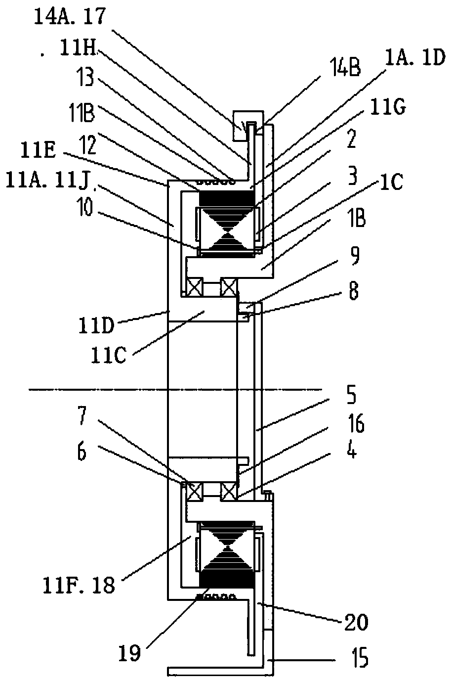
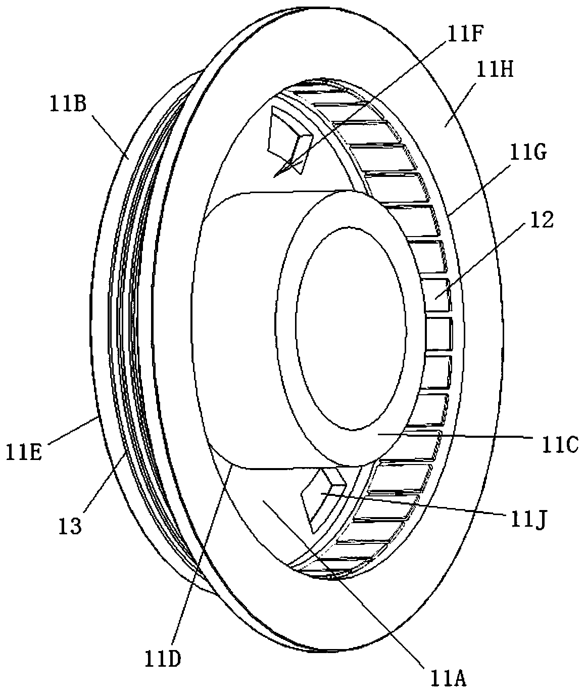
[0029] see figure 1 , Figure 3 to Figure 5 , The elevator flat traction motor shown in the figure is a radial magnetic flux permanent magnet traction motor, which includes a stator part and a rotor part.

[0030] The stator portion includes a stator core 2 and a stator coil 3 wound around the stator core 2 and a stator core support portion 1B for fixing the stator core 2 . The stator core 2 is formed by punching and laminating silicon steel sheets.

[0031] An end plate 1C is provided on the second end edge of the stator core support portion 1B, and the stator core 2 is fixed to the end plate 1C by bolts 10 and is positioned on the outer peripheral surface of the stator core support portion 1B. A brake mounting portion 1A extending radially is provided on the second end edge of the stator core support portion 1B. The brake mounting portion 1A, the stator core support portion 1B, and the end plate 1C are integrally cast. In addition, a ventilation hole ...

Example Embodiment

[0041] Example 2

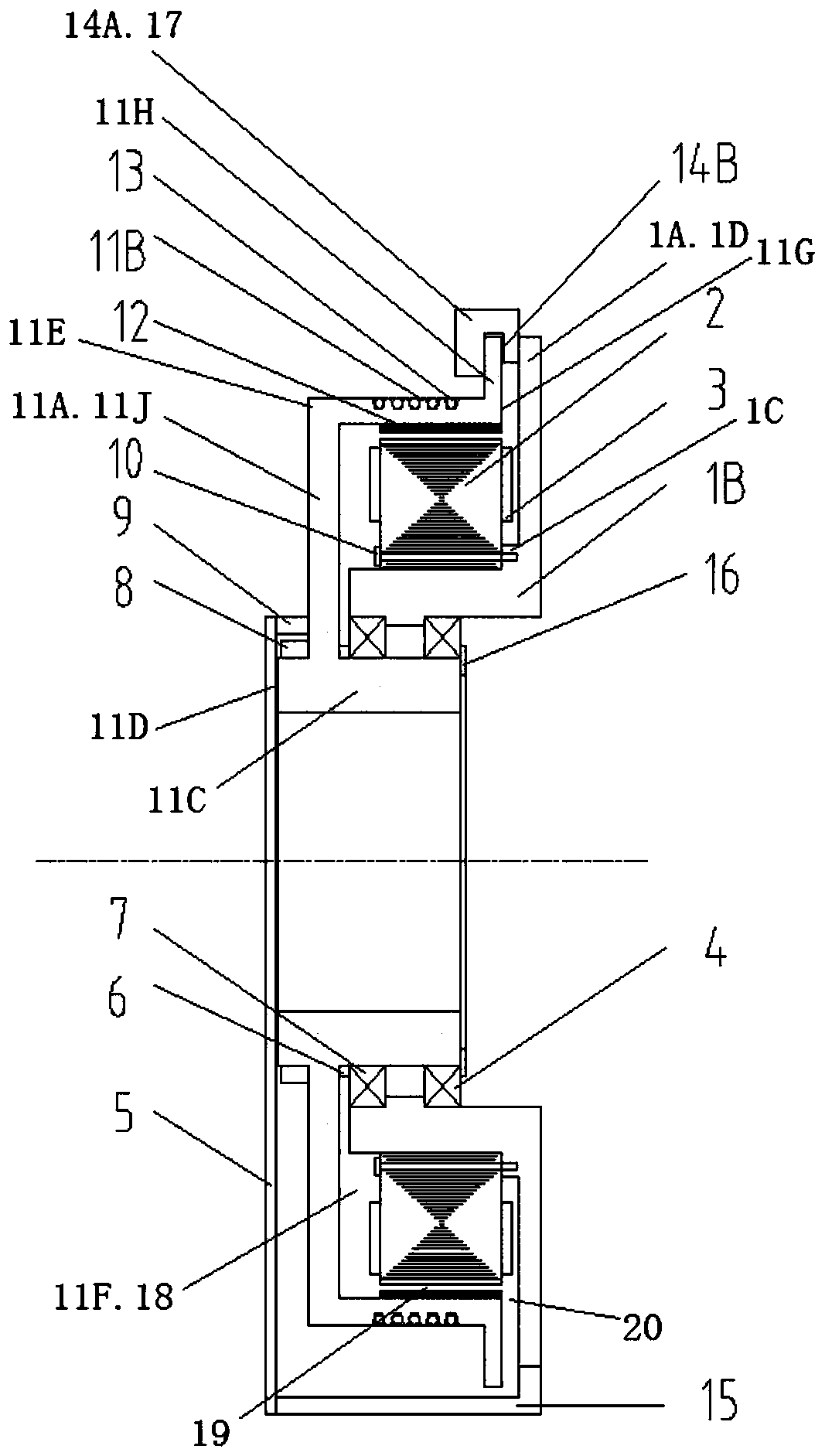
[0042] see Figure 2 to Figure 6 , Figure 7 The difference between the flat traction motor for elevators shown in the figure and the flat traction motor for elevators in Embodiment 1 is that the encoder detection device 9 is installed on the base 15 through the bracket 5 and is located at the first end of the stator support portion 11C At the position of the edge 11D, the induced magnetic ring 8 is mounted on the first end edge 11D of the stator support portion 11C.


PUM


Abstract

The invention discloses a flat traction motor for an elevator. The radial magnetic flux permanent-magnetism traction motor comprises a stator part and a rotor part, a rotor comprises a traction rope groove portion, a stator support portion and a rotor plate in U shaped connection; the inner edge of the rotor plate is integrated and connected to the first end edge of the stator support portion, theouter edge of the rotor plate is integrated and connected to the first end edge of the traction rope groove portion, and the traction rope groove portion is positioned in the periphery of the statorsupport portion; a traction rope groove is arranged in the outer peripheral surface of the traction rope groove portion, and magnetic steel is attracted by the inner peripheral surface of the tractionrope groove portion; a stator core is fixed to the outer peripheral surface of a stator core support portion, and the stator core, a stator coil and the stator core support portion are positioned inan annular groove between magnetic steel of the rotor and the stator support portion, and the inner peripheral surface of the stator core support portion is supported by the outer peripheral surface of the stator portion via a pair of bearings. The motor is short in the axial length, compact in structure and good in heat radiation effect.

Description

technical field [0001] The invention relates to the technical field of permanent magnet synchronous traction motors for elevators, in particular to a flat traction motor for elevators. Background technique [0002] At present, the permanent magnet synchronous traction motors used in elevators mainly include radial flux permanent magnet traction motors and axial flux disc permanent magnet motors. For radial flux permanent magnet traction motors, the traction sheave is fixedly connected to the rotor side by welding, press-fitting or other methods; or the traction sheave and the rotor are integrally cast, but the traction sheave is still on the rotor side, forming a cantilever formula structure. This cantilever structure has high mechanical performance requirements for structural parts, which will inevitably lead to a substantial increase in material consumption, low bearing life, or selection of larger bearings, resulting in increased costs. In addition, this cantilever stru...

Claims


Application Information

Patent Timeline
IPC IPC(8): H02K7/10H02K1/32H02K11/215H02K21/12H02K7/102
CPCH02K1/32H02K7/10H02K7/102H02K11/215H02K21/12
Inventor 屈义
Owner SHANGHAI GIE EM
Why Eureka
Try Eureka