Functional block used in realizing cause and offect matrix in treating safety system

A function block and matrix technology, applied in the field of security systems, can solve the problems of time-consuming, large number of records, complex security logic, etc.

Active Publication Date: 2004-10-06
FISHER-ROSEMOUNT SYST INC
View PDF1 Cites 3 Cited by
  • Summary
  • Abstract
  • Description
  • Claims
  • Application Information

AI Technical Summary

Problems solved by technology

Since safety logic transformed in this way can lead to highly complex programs, these programs can still be difficult and time-consuming to test and debug, and these programs can require extensive documentation
Furthermore, it is difficult to use such a program in a control routine using a function block programming strategy to perform a control function

Method used


Image

  • Functional block used in realizing cause and offect matrix in treating safety system
  • Functional block used in realizing cause and offect matrix in treating safety system
  • Functional block used in realizing cause and offect matrix in treating safety system

Examples


Embodiment Construction

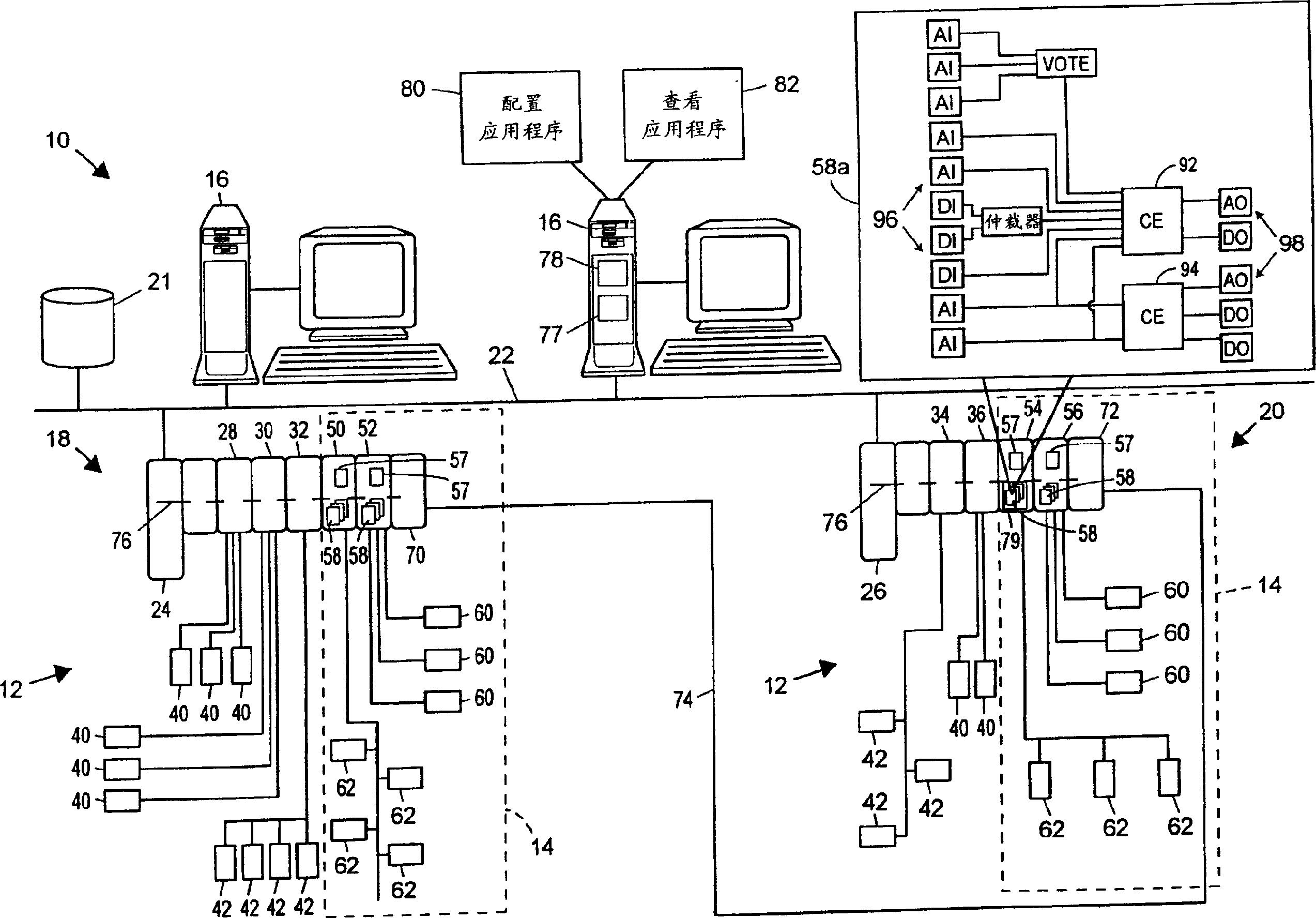
[0015] now refer to figure 1 , the processing unit 10 includes a process control system 12 integrated with a safety system 14 (indicated by dashed lines), which typically operates as a Safety Instrumented System (SIS) to monitor and override the control in order to optimize similar safe operation of the processing device 10. The processing plant 10 also includes one or more host workstations, computers or user interfaces 16 (which may be any type of personal computer, workstation, PDA, etc.) that are accessed by plant personnel, such as process control operators, maintenance personnel, safety engineers Wait. exist figure 1 In the example shown, two user interfaces 16 are shown connected via a common communication line or bus 22 to two independent process control / security control nodes 18 and 20 and to a configuration database 21 . Communications network 22 may be implemented using any desired, bus-based or non-bus-based hardware, using any desired hardwired or wireless comm...


PUM


Abstract

A cause and effect function block, which can be easily integrated into a function block diagram programming environment in a process plant safety system to implement the cause and effect logic specified by a traditional cause and effect matrix, includes a set of cause inputs and a set of effect outputs. A multiplexer within the cause and effect function block receives each of the cause inputs and is coupled to one or more state machines, with a separate state machine existing for each effect output. The multiplexer decodes each of the cause inputs and, based on the cause inputs and previously identified cause and effect matrix logic, provides a trip signal to one or more of the state machines. Upon receiving a trip signal, a state machine forces an associated effect output into a tripped or safe state. If desired, the state machine may then use one or more other signals, such as signals from a user or from the process, to transition between a set of different states used to safely return the process plant back to the normal operating state from the tripped or safe state.

Description

technical field [0001] The present invention relates generally to a security system for use in a processing device, and in particular to a functional block implementing a causal matrix for controlling the operation of the security system used in the processing device. Background technique [0002] Similar to process control systems used in chemical, petroleum, or other processing, process control systems typically include one or more process controllers that communicate via analog, digital, or combined analog / digital buses or lines is coupled to at least one host or operator workstation, and one or more field devices. The field devices, which may be, for example, valves, valve positioners, switches and transmitters (eg, temperature, pressure and flow rate sensors) perform functions within the processing device such as opening or closing valves and measuring process parameters. The process controller receives signals indicative of process measurements made by the field devic...

Claims


Application Information

Patent Timeline
Patent Type & Authority Applications(China)
IPC IPC(8): G05B9/02
CPCG05B9/02G05B11/32
Inventor 迈克尔·奥特加里·劳丹尼斯·史蒂文森罗伯特·哈夫科斯特朱利安·奈多戈弗雷·R·谢里夫
Owner FISHER-ROSEMOUNT SYST INC
Why Eureka
Try Eureka