
Switch power-supply device

A switching power supply and switching element technology, applied in the direction of output power conversion devices, electrical components, high-efficiency power electronic conversion, etc., can solve the problems of switching device functions and price waste, etc., achieve weight reduction, improve power factor, reduce The effect of small peaks

Inactive Publication Date: 2004-10-20
FUJI ELECTRIC DEVICE TECH CO
View PDF2 Cites 4 Cited by
  • Summary
  • Abstract
  • Description
  • Claims
  • Application Information

AI Technical Summary

Problems solved by technology

In particular, since it is useful to reduce the higher harmonic components to values ​​determined by specifications, etc., Image 6 more waste of function and price in the switchgear of

Method used


Image

  • Switch power-supply device
  • Switch power-supply device
  • Switch power-supply device

Examples


Embodiment Construction

[0043] Hereinafter, embodiments of the present invention will be described with reference to the drawings.

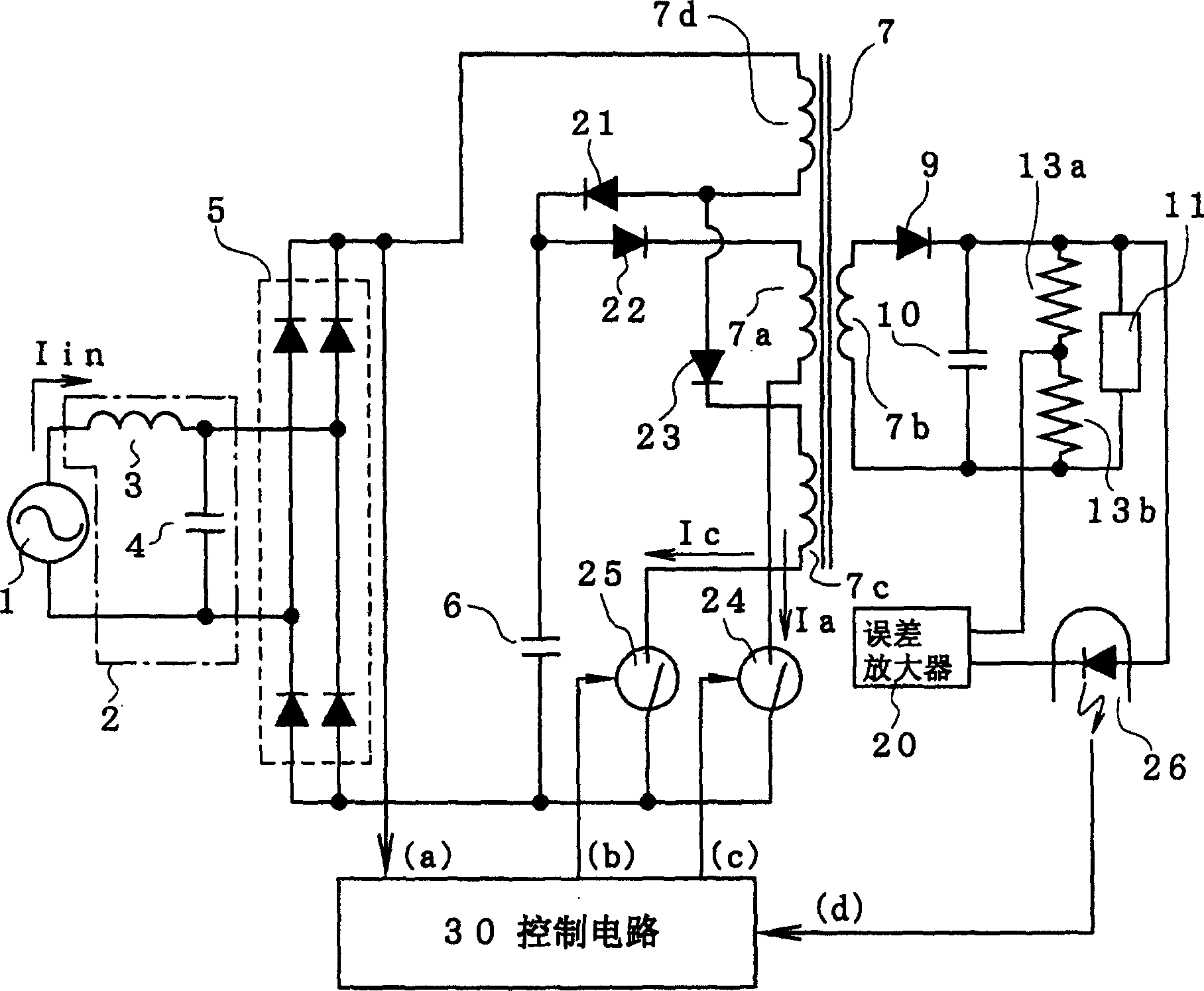
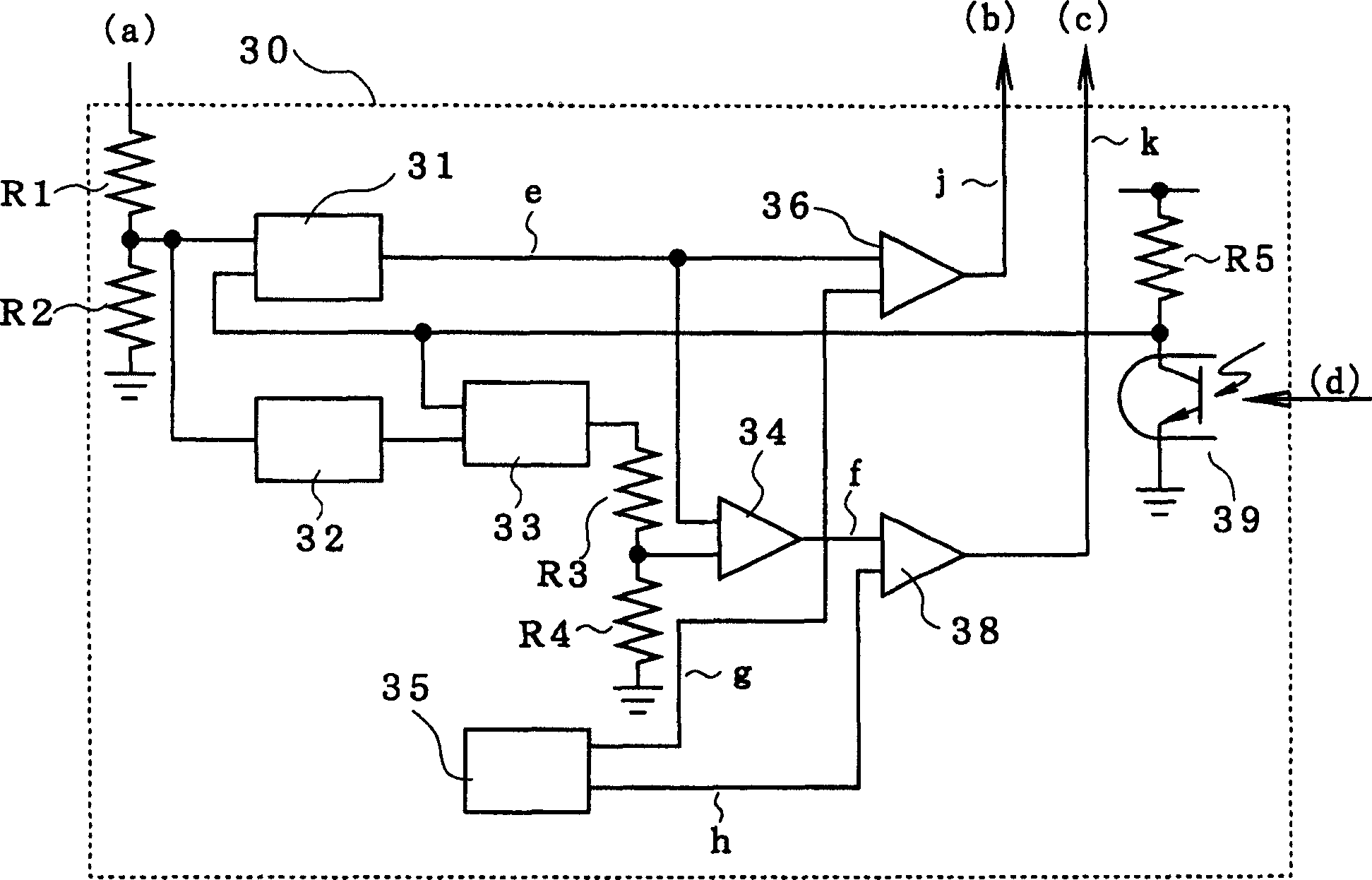
[0044] figure 1 It is a figure which shows Embodiment 1 of this invention. 7c in the figure is the third coil of the primary side of the transformer 7; 7d is the fourth coil of the primary side of the transformer 7; 21, 22, and 23 are the first, second, and third diodes respectively; 24, 25 are respectively The first and second switching elements; 30 are control circuits for these switching elements 24,25. other, with Figure 5 and Image 6 The same constituent elements are denoted by the same symbols, and their descriptions are omitted.

[0045] The full-wave rectified voltage output from the bridge rectifier circuit 5 is supplied to a series circuit of the first coil 7a and the switching element 24 through the fourth coil 7d and the diodes 21 and 22 .

[0046] The smoothing capacitor 6 is connected between the connection point of the diodes 21, 22 and the negativ...


PUM


Abstract

A switching power source device can enhance the power factor by increasing the conduction angle of an input current in a wide input voltage range, while obviating the increase of size and the increase of cost thereof, and lower the switching loss by removing higher harmonic waves from the input current. The device includes at least first, second, and third series circuits constituted of a rectifying circuit, at least first and second primary windings, a plurality of diodes, a smoothing capacitor, and first and second switching elements. The device further includes an error amplifier, which outputs an error amplified signal, and a control circuit that performs a PWM control of the switching element in response to a first modulated wave that is generated based on an inverted and amplified waveform, which is the product of the error amplified signal and a full-wave rectified waveform of an AC input voltage, and performs a PWM control of the switching element in response to a second modulated wave that is generated based on the error amplified signal and the full-wave rectified waveform of the AC input voltage to alternately turn ON and OFF the both switching elements.

Description

technical field [0001] The present invention relates to a switching power supply device for supplying a desired DC voltage to a load, and more specifically, to a switching power supply device for improving input power factor. Background technique [0002] Figure 5 The first conventional technique is a general configuration of a switching power supply device that improves power factor by using a choke coil input type smoothing circuit (see, for example, Patent Document 1). [0003] exist Figure 5 Among them, 1 represents an AC power supply, 2 represents a noise filter composed of a reactor 3 and a capacitor 4, 5 represents a bridge rectifier circuit, 6 represents a smoothing capacitor, 7 represents a transformer, 7a represents the first coil of the primary side of the transformer 7, 7b is the second coil on the secondary side of the transformer, 8 is the first switching element, 9 is a diode, 10 is a smoothing capacitor, 11 is a load, 12 is a control circuit for turning on ...

Claims


Application Information

Patent Timeline
Patent Type & Authority Applications(China)
IPC IPC(8): H02M3/28H02M1/42
CPCY02B70/126H02M2001/4275H02M1/4258H02M1/4275Y02B70/10
Inventor 桑原今朝信
Owner FUJI ELECTRIC DEVICE TECH CO
Learn More