Pressure controlled constant tempeature crystal oscillator

A technology of oven controlled crystal oscillation and crystal oscillator, which is applied in power oscillators, temperature control by electric means, electrical components, etc. , the effect of reducing the volume

Inactive Publication Date: 2004-10-20
HUAZHONG UNIV OF SCI & TECH
View PDF1 Cites 9 Cited by
  • Summary
  • Abstract
  • Description
  • Claims
  • Application Information

AI Technical Summary

Problems solved by technology

Most of the existing constant temperature crystal oscillators use discrete components for their temperature c

Method used


Image

  • Pressure controlled constant tempeature crystal oscillator
  • Pressure controlled constant tempeature crystal oscillator
  • Pressure controlled constant tempeature crystal oscillator

Examples


Embodiment Construction

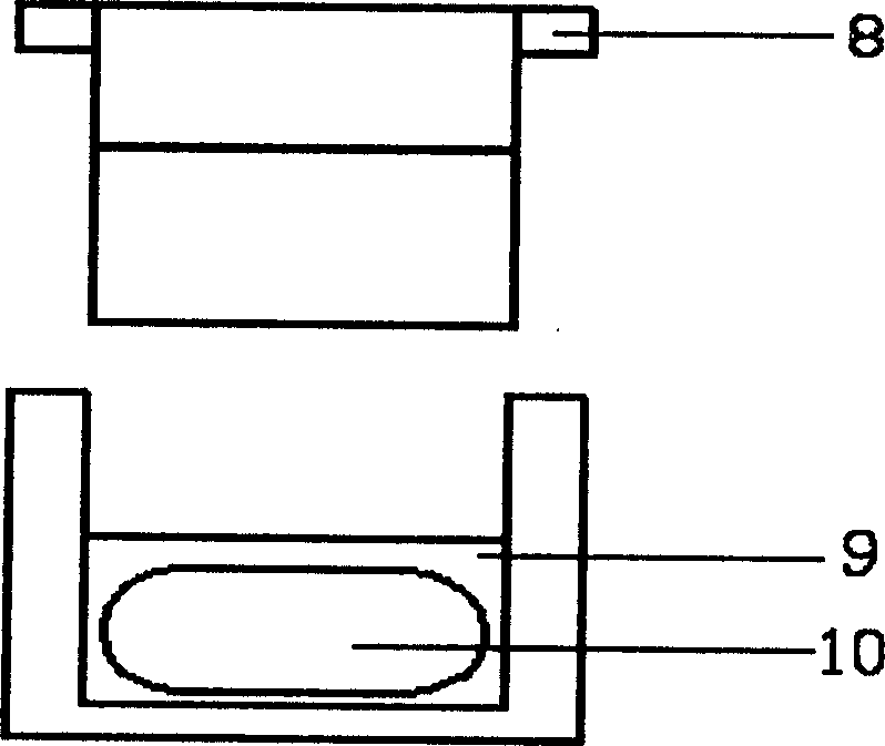
[0017] In order to improve the temperature control accuracy and comply with the development trend of miniaturization of electronic devices, it is necessary to change the traditional way of using discrete components, choose a new temperature control method and carefully design the structure of the constant temperature bath.

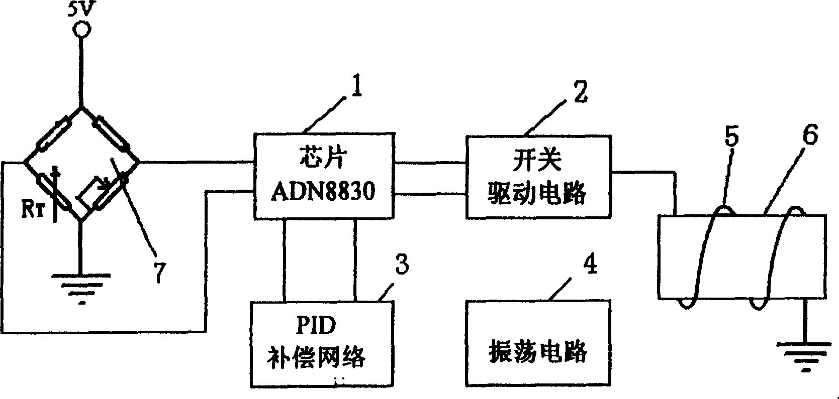
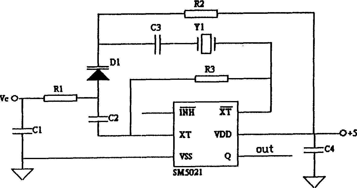
[0018] Depend on figure 1 As shown, the present invention includes: a temperature control chip ADN88301, a switch drive circuit 2, a PID compensation circuit 3, an oscillation circuit 4, a heating element 5, a constant temperature bath 6, and a temperature sensing circuit 7. The above-mentioned heating element 5 can be a resistance wire or a positive temperature coefficient thermistor PTC. In the drawings, the heating element 5 is an example of a resistance wire, and the temperature sensing circuit 7 is an example of a thermistor bridge.

[0019] The temperature control chip ADN88301 is connected to the thermistor bridge, and outputs a square wave with a c...


PUM


Abstract

New mode for controlling temperature and new structure of thermostated trough are adopted in the invention. For control temp, IC chip ADN8830 in PWM mode outputs square wave in certain duty ratio to switch drive circuit. The duty ratio is controlled by PID compensation circuit to control heating power of resistive heater to reach target for controlling temp. Thermostated trough includes trough body, and trough cover. Resistance wire is enwound on thermostated trough. Resonator Y1 is put in cavity inside trough body. Thermistor RT is in trough at side of the trough body. Cover seals oscillating circuit board on trough body. Advantages of the invention are small size and high frequency stability.

Description

technical field [0001] The invention relates to a constant temperature crystal oscillator. Background technique [0002] Oven Controlled Crystal Oscillator (Oven Controlled Crystal Oscillator) is currently the crystal oscillator with the highest accuracy and stability. It has the characteristics of low aging rate, good temperature stability, and high long-term frequency stability, so it is widely used in global positioning systems, communication , metering, telemetry, remote control and other occasions that require high frequency stability. Most of the existing constant temperature crystal oscillators use discrete components for their temperature control circuits, so they are very bulky and inconvenient to realize the miniaturization of electronic devices. For example, the patent application of application number 98806936.9. Contents of the invention [0003] The object of the present invention is to overcome the disadvantages of the above-mentioned prior art, and provid...

Claims


Application Information

Patent Timeline
IPC IPC(8): G05D23/19H03B5/04H03B5/32
Inventor 于军高俊雄刘刚王耘波周文利谢基凡伍晓芳
Owner HUAZHONG UNIV OF SCI & TECH
Why Eureka
Try Eureka