R-T-B system rare earth permanent magnet

A permanent magnet, R-T-B technology, applied in the direction of magnetic materials, magnetic objects, electrical components, etc., can solve the problem of good magnetization characteristics and achieve the effect of improving magnetization characteristics

Active Publication Date: 2004-10-27
TDK CORPARATION
View PDF2 Cites 35 Cited by
  • Summary
  • Abstract
  • Description
  • Claims
  • Application Information

AI Technical Summary

Problems solved by technology

[0007] However, in Japanese Patent Laid-Open No. 2003-217918, the magnetic susceptibility Br (0.2MA / m) / Br (2.0MA / m) evaluated by the residual magnetic flux density is 59% or more, and the magnetic susceptibility φ (0.3MA / m) evaluated by the magnetic flux / m) / φ(4.0MA / m) is more than 4%, it cannot be said that the magnetization characteristics are good

Method used


Image

  • R-T-B system rare earth permanent magnet
  • R-T-B system rare earth permanent magnet
  • R-T-B system rare earth permanent magnet

Examples


experiment example 1

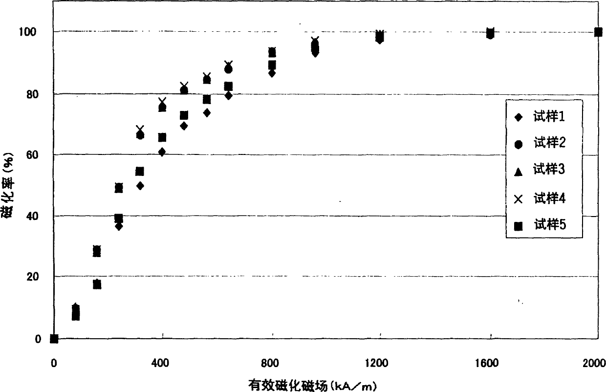
[0120] Raw material alloys (low-R alloys and high-R alloys) having the composition shown in FIG. 1 were produced by strip casting.

[0121] Each of the obtained raw material alloys was allowed to store hydrogen at room temperature, and then dehydrogenated in an Ar atmosphere at 600° C. for 1 hour to perform a hydrogen pulverization treatment.

[0122] In order to obtain high magnetic properties, the oxygen content of the sintered body was controlled below 1000ppm in Experimental Example 1, so the protective atmosphere in each process from hydrogen pulverization (recovery after pulverization treatment) to sintering (putting into the sintering furnace) was controlled to be insufficient Oxygen concentration of 100 ppm (this point is also the same in Experimental Examples 2 to 11 below).

[0123] Generally, two-stage pulverization of coarse pulverization and fine pulverization is performed, and the coarse pulverization step was omitted in Experimental Example 1 (the same applies t...

experiment example 2

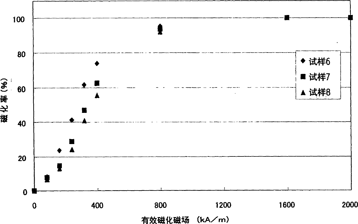
[0133] By using the raw material alloy of the composition shown in Figure 6 and controlling the oxygen content in the pulverization gas (nitrogen) when making the fine powder to change the oxygen content in the final sintered body, the other was obtained in the same manner as in Experimental Example 1. 3 types of permanent magnets (samples 6 to 8). Magnetic properties and the like were measured in the same manner as in Experimental Example 1 for the obtained three types of permanent magnets. The results are shown in Fig. 7 . In addition, Ts in FIG. 7 means a sintering temperature, and other symbols are the same as those in FIG. 2 .

[0134] As shown in Fig. 7, it can be seen that all the permanent magnets of samples 6 to 8 have a residual magnetic flux density of 1.4T or more, a coercive force of around 1000kA / m, and a coercive force of 400kJ / m 3 near the higher maximum energy product.

[0135] Next, the magnetic susceptibility (Pc=2) of the permanent magnets of samples 6 t...

experiment example 3

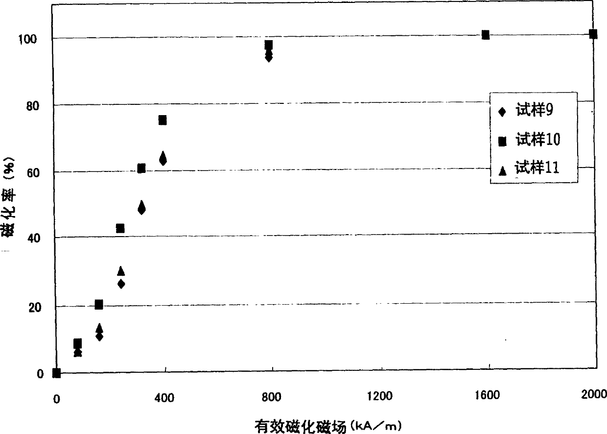
[0138] Three types of permanent magnets (samples 9 to 11) were obtained in the same manner as in Experimental Example 1 except that the raw material alloys shown in FIG. 10 were used. Magnetic properties and the like were measured in the same manner as in Experimental Example 1 for the obtained permanent magnets. The results are shown in Fig. 11 . In addition, the symbols in FIG. 11 are the same as those in FIG. 7 .

[0139] As shown in Fig. 11, it can be seen that sample 9 which does not contain M element has a very low square ratio of 60.22%, and is not a practical permanent magnet; sample 10 containing Zr as M element and sample 11 containing Ti, All have a residual magnetic flux density above 1.4T, a coercive force near 1100kA / m, and a coercive force of 400kJ / m 3 Around this higher maximum energy product.

[0140] The microstructure of Sample 9 was observed, and in Sample 9, abnormally grown crystal grains up to about 100 μm were observed in the sintered body. This is ...


PUM

PropertyMeasurementUnit
coercivityaaaaaaaaaa
diameteraaaaaaaaaa
diameteraaaaaaaaaa

Abstract

An R-T-B system rare earth permanent is provided, which comprises a sintered body comprising: an R2T14B phase (wherein R represents one or more rare earth elements (providing that the rare earth elements include Y) and T represents one or more transition metal elements essentially containing Fe, or Fe and Co) as a main phase; and a grain boundary phase containing a higher amount of R than the above main phase, wherein, when Pc (permeance coefficient) is 2, if a total flux is defined as f1 under the application of an effective magnetic field of 240 kA / m (providing that an effective magnetic field = an applied magnetic field - a demagnetizing field, and each value of them is absolute value), if a total flux is defined as f2 under the application of an effective magnetic field of 800 kA / m, and if a total flux is defined as f3 under the application of an effective magnetic field of 2, 000 kA / m, a magnetization rate a (= f1 / f3 x 100) is 40% or more, and a magnetization rate b (= f2 / f3 x 100) is 90% or more.

Description

technical field [0001] The present invention relates to R-T-B (R is one or more than two kinds of rare earth elements (however, rare earth elements are the concept of containing Y), T (one or more than two kinds of essential elements are Fe or Fe and Co) Transition metal element) based rare earth permanent magnets, especially rare earth permanent magnets with high magnetization characteristics. Background technique [0002] Among rare earth permanent magnets, R-T-B series rare earth permanent magnets are used in various electrical equipment because they have excellent magnetic properties, abundant and relatively cheap Nd resources as the main component. [0003] So far, research and development to improve the magnetic properties of R-T-B-based rare earth permanent magnets, specifically, to improve the residual magnetic flux density, coercive force, or maximum energy product has been the mainstream. However, research and development focusing on magnetization characteristics ...

Claims


Application Information

Patent Timeline
Patent Type & Authority Applications(China)
IPC IPC(8): H01F1/057
CPCH01F1/0577
Inventor 日高徹也坂元一也佐藤和生冈田宏成
Owner TDK CORPARATION
Why Eureka
Try Eureka