
Beam forming method adapted to wide band CDMA system

A broadband code division multiple access and beam technology, which is applied in the direction of code division multiplexing system, diversity/multi-antenna system, baseband system components, etc. Excellent problems, to achieve the effect of reducing technical difficulty and calculation amount, simplifying system composition, and shortening R&D cycle

Inactive Publication Date: 2004-11-24
ZTE CORP
View PDF0 Cites 24 Cited by
  • Summary
  • Abstract
  • Description
  • Claims
  • Application Information

AI Technical Summary

Problems solved by technology

In the pre-multiple beams, each weight can only be selected from several pre-specified groups of values, and the working mode of the smart antenna at a certain moment can only be selected from several pre-designed beams, which are not arbitrarily oriented, so only It is possible to partially match the current transmission environment, which is not optimal from a theoretical point of view
[0003] Therefore, the core technology in the smart antenna system is the adaptive beamforming technology. The improvement degree of the smart antenna system to the communication system mainly depends on the performance of the adaptive beamforming method. At present, various adaptive beamforming methods have been proposed. Such as the constant modulus algorithm, but this algorithm is a blind algorithm, which does not use the pilot bits specified in the WCDMA protocol, which is a waste of resources; there are other beamforming algorithms, such as code filtering and cascade training methods, in The operation process involves large-scale matrix multiplication and inversion operations, the complexity and amount of calculation are too large, and it is not easy to implement by hardware
At present, there is no technical solution to fundamentally solve the above problems

Method used


Image

  • Beam forming method adapted to wide band CDMA system
  • Beam forming method adapted to wide band CDMA system
  • Beam forming method adapted to wide band CDMA system

Examples


Embodiment Construction

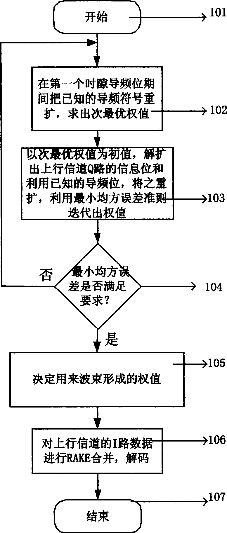
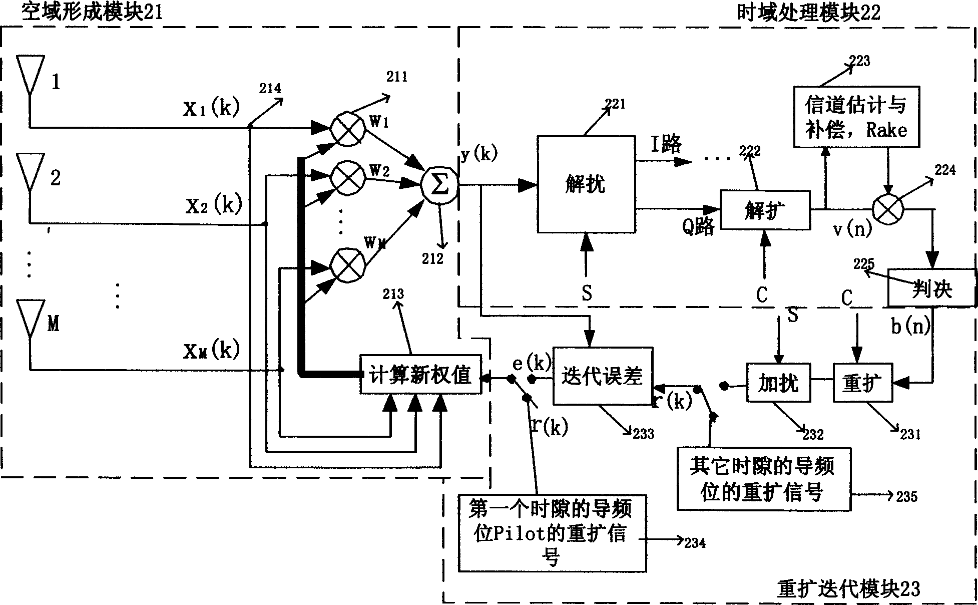
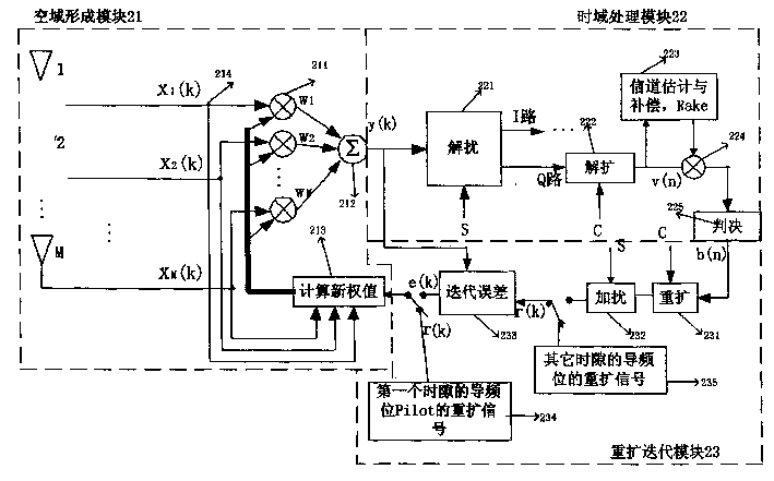
[0010] Such as figure 1 As shown, the process starts, step 101; first, during the pilot bit period of the first time slot, the respread scrambling symbol of the known uplink channel pilot symbol is used as a reference signal, and the current information bit aligned with the time delay The array receiving vector X of the array receives the cross-correlation operation to find the suboptimal weight value. During the pilot bit period of the first time slot of each frame, the signal after the pilot signal is spread and scrambled is used as the reference signal r, and the The cross-correlation matrix r of the pilot signal X received by the array and the reference signal r xr =E[Xr * ], the approximate solution obtained according to the minimum mean square error criterion is used as the adaptive suboptimal weight W=r xr , and use the weight W calculated in the above two steps to carry out beamforming Y=W×X, Y is the input of the time domain processing module 22 and the respreading ...


PUM


Abstract

The present invention relates to a beam forming method applicable in wide-band code-division multiple access system, which comprises the steps of carrying out the spatial processing on array signals, wherein the array signals are baseband signals X aligned in time delay; during the pilot bit period of a first time slot, performing the cross-correlation operation on a symbol obtained through respreading and scrambling a known pilot symbol in an uplink channel for each frame as a reference signal and the baseband signals X, so as to obtain a cross-correlation matrix r*r=E[Xr*]; calculating a suboptimum weighted value till all pilot bits in the first time slot are over; during the periods of information symbol bits and other time slots, performing the iteration operation on the suboptimum weighted value as an initial value, the respread and scrambled signals of despread and descrambled information symbol bits and the respread and scrambled signals of known pilot bits as reference signals respectively, based on the principle of the minimum mean square error, so as to figure out a self-adaptive suboptimal weighted value W=r*r; and forming beams by means of the suboptimal weighted value W to obtain Y=W*X. The beam forming method simplifies the structure of the system and also greatly reduces the technical difficulty and the amount of calculation.

Description

technical field [0001] The invention relates to a wideband code division multiple access system, in particular to an adaptive beam forming method of an intelligent antenna base station. Background technique [0002] Wideband Code Division Multiple Access (WCDMA) is the third generation of communication technology. Compared with the previous two generations of communication technology, it has better security, higher transmission rate and other performances, so it has become the trend of communication system development. Since the CDMA system is an interference-limited system, the existence of multiple access interference will seriously affect the system performance, so how to effectively suppress multiple access interference (MAI) is the key to the research of the third generation mobile communication. Taking advantage of the differences in the signal structure, space and time propagation characteristics of the useful signal and the interference signal, there are mainly two M...

Claims


Application Information

Patent Timeline
IPC IPC(8): H04L25/02H01Q21/00H04B7/04H04B7/06H04B7/08H04L25/03
Inventor 迟立东王衍文李景毅
Owner ZTE CORP
Learn More