Hybrid type driving apparatus

A driving device and hybrid technology, which is applied in power devices, hybrid vehicles, pneumatic power devices, etc., can solve the problem of not sharing the drive circuit for improvement and development, etc.

Inactive Publication Date: 2004-12-01
HONDA MOTOR CO LTD
View PDF2 Cites 9 Cited by
  • Summary
  • Abstract
  • Description
  • Claims
  • Application Information

AI Technical Summary

Problems solved by technology

However, improvement based on the viewpoint of sharing the driving circuit has not been developed so far

Method used


Image

  • Hybrid type driving apparatus
  • Hybrid type driving apparatus
  • Hybrid type driving apparatus

Examples


Embodiment Construction

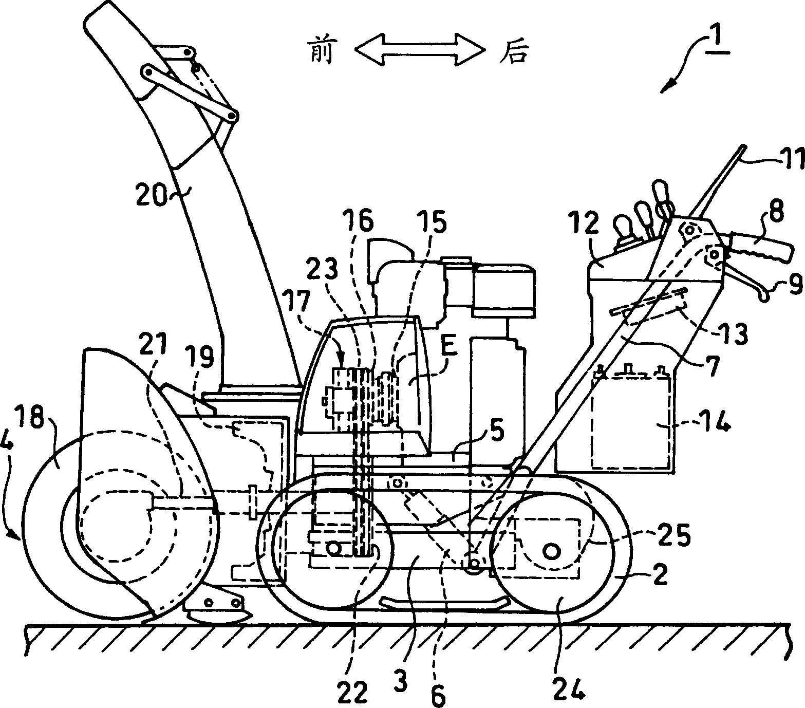
[0017] An embodiment of the present invention will be described in detail below with reference to the accompanying drawings. figure 2 It is a side view of the snow blower as an engine-driven working machine according to an embodiment of the present invention. In the snow blower 1 , a vehicle body frame 5 having a snow removal work unit 4 and an engine E driving the snow removal work unit 4 is mounted on a running unit frame 3 having left and right crawler belts 2 so as to be able to swing up and down. The engine E is controlled to run at a constant rotational speed to drive the snow removal unit 4 as a working machine. The frame raising and lowering mechanism 6 swings the vehicle body frame 5 up and down by raising and lowering the front portion of the vehicle body frame 5 . The running part frame 3 is combined with left and right operating handles 7 extending rearward and upward.

[0018] The operating handle 7 is an operating handle for the operator to operate the snow bl...


PUM


Abstract

An engine-driven generator G is concurrently used as a starter motor for an engine E that drives a working machine. A motor 25 for motive-power use is a driving source for the working machine to travel. The driving circuit 10 is commonly used between the starter motor G and the motor 25 for travel use. In a starting mode, with switches 35 and 36, the driving circuit 10 is connected to the starter motor G side to start the engine. After complete explosion of the engine, with the switches 35 and 36, the generator G is connected to a regulator 31, while the driving circuit 10 is connected to the motor 25 for travel use. As a result of this, while a battery 14 is electrically charged, the motor 25 for travel use is driven with the battery 14.

Description

technical field [0001] The present invention relates to a hybrid drive device having an internal combustion engine and an electric motor as a power source of a work machine, etc., and more particularly to a hybrid drive device capable of sharing a drive circuit by using an electric motor as a power source of a work machine or the like and a starter of an engine. Background technique [0002] Among agricultural work machines, a so-called hybrid engine-driven work machine is known in which power from an engine and power from an electric motor can be utilized. For example, in Japanese Patent Laid-Open No. 2001-161114, it is proposed that when the load of the working machine driven by the engine is small, relying on the remaining power of the engine to drive the generator and storing the remaining power in the battery, and relying on these to generate electricity A proposal for a manned work machine that drives an electric motor using the power generated by the machine and the p...

Claims


Application Information

Patent Timeline
Patent Type & Authority Applications(China)
IPC IPC(8): E02F9/20B60K6/46B60L50/13B60L50/15B60L50/16B60W10/06B60W10/08B60W10/26B60W20/00F02D29/00F02D29/06F02D45/00F02N11/04F02N11/08
CPCB60W10/06B60Y2200/41B60W10/26Y02T10/7077Y02T10/6286Y02T10/6217B60L11/12Y02T10/7005B60W20/00B60W10/08B60K6/46B60K2006/268B60L50/15Y02T10/62Y02T10/70Y02T10/7072B60W2300/43B60W20/13
Inventor 胁谷勉川上俊明小林浩
Owner HONDA MOTOR CO LTD
Why Eureka
Try Eureka