Rectification transformers with self coupling compensation and resournace shield

A rectifier transformer and autotransformer technology, which is applied in harmonic reduction devices and AC networks to reduce harmonics/ripples, etc., can solve the problems of high cost and technical difficulties, and achieve technical difficulties and low cost. Effect

Active Publication Date: 2004-12-08
CHINESE NONFERROUS METAL SURVEY & DESIGN INSTITUE OF CHANGSHA
View PDF0 Cites 12 Cited by
  • Summary
  • Abstract
  • Description
  • Claims
  • Application Information

AI Technical Summary

Problems solved by technology

This technology has been used in industrialized countries for a long time, but it has many technical difficulties and high cost, so it has not been widely used so far.

Method used


Image

  • Rectification transformers with self coupling compensation and resournace shield
  • Rectification transformers with self coupling compensation and resournace shield
  • Rectification transformers with self coupling compensation and resournace shield

Examples


Embodiment 1

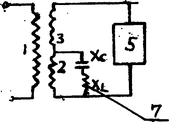
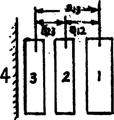
[0019] Such as Figure 1-3 As shown, this embodiment is a single-phase auto-coupling compensation and harmonic shielding rectifier transformer, including primary winding 1, secondary winding and cylindrical core 4, and an auto-coupling tap is drawn in the middle of the secondary winding to divide the secondary winding into windings 2 and 3, The three windings are jointly arranged on the round iron core column 4, the auxiliary winding 3 is arranged on the inner layer close to the cylindrical iron core 4, the original winding 1 is arranged on the outermost layer, and the auxiliary winding 2 is arranged between the auxiliary winding 3 and the original winding 1, The two ends of the secondary winding 2 and the capacitive reactance X C Series inductance X L The two branches of the primary winding 1 are connected to the grid power supply, and the power supply load 5 is connected in parallel with the two secondary windings 2 and 3 in series.

[0020] This embodiment can supply powe...

Embodiment 2

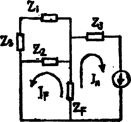
[0027] This embodiment is a three-phase rectifier with self-coupling compensation and harmonic shielding. The primary winding can be star-shaped or triangular (not shown in the figure), and the secondary winding can be a Yanbian triangle with a middle lead-out tap, such as Figure 4 As shown, the Yanbian endpoints u, v, w are respectively connected to the three-phase rectifier bridge 6 on the valve side, forming a six-pulse rectification output and connected to the power supply load 5; the triangular three-phase terminals a, b, c are connected to the compensation capacitor Sense L C Components are connected. Its triangular phase winding is equivalent to the common winding 2 of the autotransformer, which plays a shielding role in filtering, and the extension winding is equivalent to the series winding 3 of the autotransformer; The iron core 4 is arranged concentrically. The flux generated by the harmonic currents, similar to the single-phase rectifier transformer described ab...

Embodiment 3

[0031] Embodiment 3: This embodiment is a 6-phase 12-pulse self-coupling compensation and harmonic shielding rectifier transformer composed of two extension triangles on the secondary side. Such as Figure 6 As shown, the two sets of three-phase outputs of the secondary winding are respectively connected to their respective three-phase rectification devices 6. The two rectification devices 6 contain thyristors that can form 12 pulsating phases, and the potential difference between phases is 30°. The self-coupling compensation and self-coupling taps of the shielding filter drawn out in the center are connected with the additional compensation and filtering equipment 7, that is, the capacitive-inductive branch L-C; the original rectifier transformer usually installs the compensation and filtering equipment on the grid-side high-voltage bus according to the traditional wiring , the present invention moves the compensation and filter equipment 7 from the network side to the side c...


PUM


Abstract

A rectifier transformer with self-couple compensation and shielding harmonic is disclosed. The self-couple tap is led out from the secondary winding in the supply transformer, this tap divides the secondary winding into two stages: the analogous auto-transformer common winding and series winding. Both of them are coupled closely, the secondary windings of the two stages and primary winding are arranged with one center on the iron core cylinder, specially the common winding is arranged between the primary winding and series winding, its equivalence impedance value is zero. The both ends of common winding connect to the bypass of external filter capacitor inductance. The invention can take reactive compensation for inductive current at user's power frequency. Utilize the Ampere-turn balancing action of two windings divided by tap at relevant harmonic frequency to neutralize the harmonic current, thereby leads the harmonic current to return to load nearby through series winding and prevents the harmonic current from crossing the air gap into primary power network. It also prevents the harmonic magnetic flux from damaging to the transformer.

Description

【Technical field】 [0001] The invention relates to the technical field of power transmission, in particular to rectification, commutation, traction and electric arc furnace transformers and compensation and filtering equipment. 【Background technique】 [0002] The proportion of non-linear loads in modern power systems is gradually increasing, and the most prominent ones are rectifier loads and electric arc furnace loads. The latter includes AC or DC steelmaking. No matter what kind of steelmaking, its current is also intermittent conduction and The disconnection forces the current waveform of the power supply network to be distorted. In addition to the power frequency fundamental wave, there are various high-order harmonic content. The flow on the side of the power grid brings various adverse effects on the passing circuit and adjacent equipment. The traditional method of controlling harmonics is passive filtering. The parallel branch connected in series with CL components is...

Claims


Application Information

Patent Timeline
Patent Type & Authority Applications(China)
IPC IPC(8): H02J3/01
CPCY02E40/40
Inventor 刘福生
Owner CHINESE NONFERROUS METAL SURVEY & DESIGN INSTITUE OF CHANGSHA
Why Eureka
Try Eureka