
Optical lens protective device

A technology for optical lenses and protective devices, applied in optics, optical components, televisions, etc., can solve the problem of unusable optical lenses, and achieve the effect of reducing drive

Inactive Publication Date: 2004-12-15
DALIAN UNIV OF TECH
View PDF6 Cites 16 Cited by
  • Summary
  • Abstract
  • Description
  • Claims
  • Application Information

AI Technical Summary

Problems solved by technology

[0004] However, during the use of the above-mentioned lens protection device, it was found that since the protective gas overflowing along the optical channel will form a forward moving air flow, the Bernoulli effect will drive the surrounding gas that contains dirt such as tar and dust in the furnace to flow, and Make these dirt deposits around the optical channel, forming tubular deposits around the optical channel, and its inner diameter will gradually decrease over time, so that the field of view and clear aperture of the optical lens will gradually decrease, eventually making it unusable , so these deposits must be cleaned regularly

Method used


Image

  • Optical lens protective device
  • Optical lens protective device

Examples


Embodiment Construction

[0014] Specific embodiments of the present invention will be described in detail below in conjunction with the accompanying drawings.

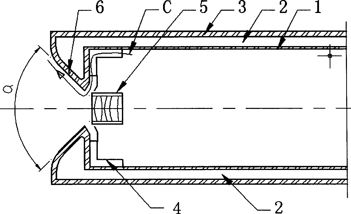
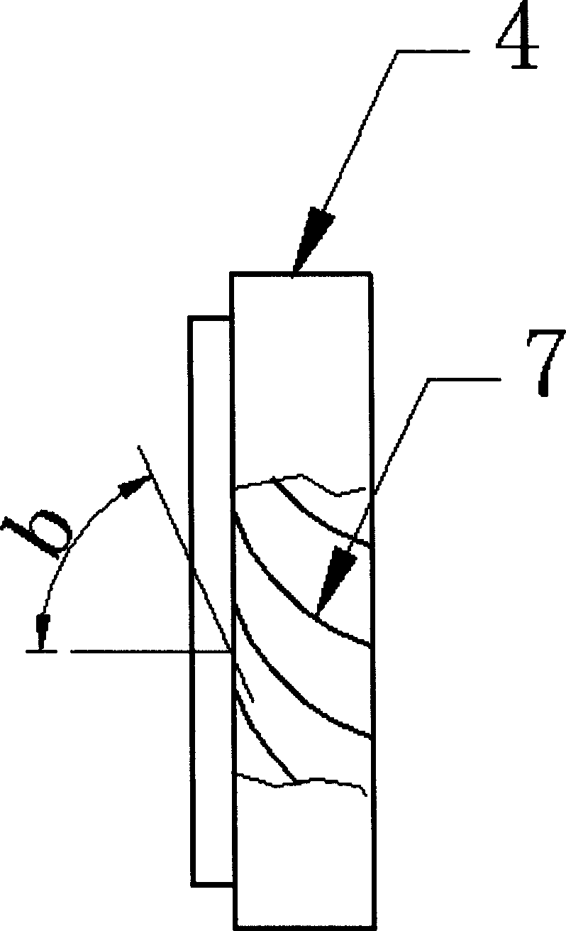
[0015] The inner cylinder 1 of the protective chamber is a stainless steel cylinder with an inner diameter of 80 mm and a thickness of 1 mm, the outer cylinder of the protective chamber 3 is a stainless steel cylinder with an outer diameter of 90 mm and a thickness of 2 mm, the front end cover 6 is a tapered stainless steel, and the diameter of the middle optical channel is 14 mm. The cone angle α is 90 degrees. The deflector 4 is a stainless steel ring with an outer diameter of 70 mm, an inner diameter of 30 mm, and a height of 5 mm. The number of deflectors is 8, and the angle b is 60 degrees. The optical lens 5 is a lens with a focal length of 4 millimeters, and the angle of view is 76 degrees.

[0016] The protective gas flowing into the cavity is pure nitrogen with a flow rate of 10 liters / minute, and the cooling water in the protective ...


PUM


Abstract

The optical lens protective device is used in optoelectronic detection and industrial monitoring and suitable for the protection of optical lens in harsh environment, such as video camera lens in heating furnace, etc. The present invention features that in the optical lens protective device comprising inner protective barrel, outer protective barrel, front end cap and other part, one guiding unit is set to make the protective gas produce rotary diffusing gas flow in front of the lens, form one small local dustless environment and protect the lens from the pollution of dust, the corrosion of harmful gas and the influence of high temperature. The present invention can ensure the long term and reliable operation of optical lens.

Description

technical field [0001] The invention belongs to the technical fields of photoelectric detection and industrial monitoring, and relates to an optical lens protection device used in harsh environments such as high temperature, dust and harmful chemical components, such as in a high-temperature heating furnace. Background technique [0002] At present, the high-temperature-resistant TV camera system in the high-temperature heating furnace has been widely used, and the following patent documents disclose technologies related to lens protection methods: such as "Endoscopic Flame Monitor Imaging Lens Cooling Device" (application number 93211332.X), "High temperature resistant zoom TV camera lens" (application number 98224057.0), "new air-cooled high temperature resistant TV lens" (application number 01256868.6), "high temperature resistant TV lens" (application number 01129181.8), "boiler flame TV device" (application No. 95221384.2), "Optical System of High Temperature Camera Len...

Claims


Application Information

Patent Timeline
IPC IPC(8): G02B13/00H04N5/225
Inventor 赖康生许青腾伟科王晓旭赖建生代东明
Owner DALIAN UNIV OF TECH
Learn More