Db-linear variable gain amplifier (vga) stage with a high broad band

An operational amplifier and wide bandwidth technology, which is applied in the direction of gain control, amplification control, and control of components of the amplification device, etc., and can solve problems such as increasing circuit complexity

Inactive Publication Date: 2004-12-15
LANTIQ BET GMBH & CO KG
View PDF0 Cites 8 Cited by
  • Summary
  • Abstract
  • Description
  • Claims
  • Application Information

AI Technical Summary

Problems solved by technology

[0025] adjustment, thus increasing the circuit complexity;

Method used


Image

  • Db-linear variable gain amplifier (vga) stage with a high broad band
  • Db-linear variable gain amplifier (vga) stage with a high broad band
  • Db-linear variable gain amplifier (vga) stage with a high broad band

Examples


Embodiment Construction

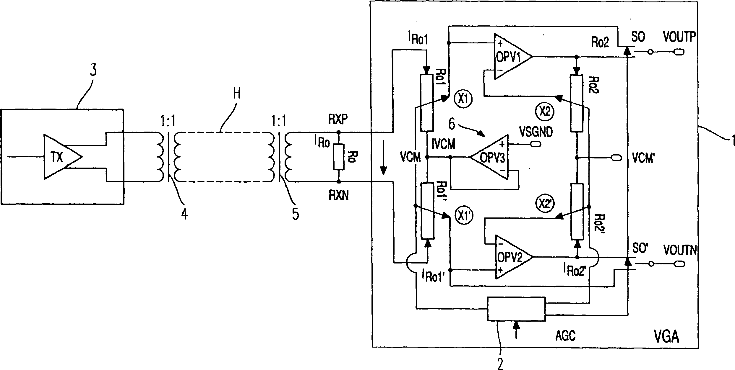
[0062] figure 1 Shown is the basic structure of a VGA stage including signal feeders. The amplified signal is transmitted via a cable H (coaxial cable or twisted pair) by a drive circuit (transmitter) 3 . At the interface between the transmitter / cable and the cable / receiver, respective transformers 4, 5 are given. The structure of the VGA stage 1 of the receiver is a fully differential structure, and has the same circuit part for the positive half-wave and the negative half-wave of the input signal respectively.

[0063] The VGA stage shown is capable of highly linearly amplifying or attenuating differential input signals fluctuating between, for example, 20 mV to 2 V, respectively, with a wide dynamic range and wide bandwidth and is capable of providing a substantially constant amplitude differential output at the differential output terminals VOUTP and VOUTN Signal.

[0064] By means of terminating resistors, the transmission cable H can be terminated non-reflectively. ...


PUM


Abstract

The invention relates to a VGA stage having a novel circuit configuration for amplifying / attenuating a differential input signal which is transmitted via a transmission line (H). The VGA stage comprises an operational amplifier (OPV1, OPV2), which is connected as shunt feedback, for amplifying the input signal; a string of resistors (R01, R01') for attenuating the signal; and a control device (2) for switching the string of resistors (R01, R01').

Description

technical field [0001] The present invention relates to a broadband VGA stage, in particular for amplifying / attenuating differential input signals with a wide dynamic range. Background technique [0002] A VGA (Variable Gain Amplifier) ​​stage is used to convert a variable input signal into an output signal with a fixed amplitude. Modern VGA stages have to meet high requirements for linearity characteristics and bandwidth which can cause problems especially if the input signal has a wide dynamic range (eg from 20mV to 2V). [0003] In order to meet the above criteria, the problem is, especially due to the fact that sending the application-dependent signal over different cable lengths between the transmitter and the receiver, and the receiver's input amplifier has to handle amplitudes ranging from e.g. -20dB to + Signal between 20dB, at the same time, the amplifier must have excellent linearity, best offset and noise characteristics. In addition, the amplifier must not sign...

Claims


Application Information

Patent Timeline
Patent Type & Authority Applications(China)
IPC IPC(8): H03G1/00H03G3/00
CPCH03G3/001H03G1/0088
Inventor 彼得·格蕾戈留斯奥托·舒马赫
Owner LANTIQ BET GMBH & CO KG
Why Eureka
Try Eureka