

Double gantry horizontal series parallel schematic milling composite digital controlled machine tool
A compound CNC machine tool and double gantry technology, which is applied to other manufacturing equipment/tools, manufacturing tools, etc.
- Summary
- Abstract
- Description
- Claims
- Application Information
AI Technical Summary
Problems solved by technology
Method used
Image

Examples
Embodiment 1
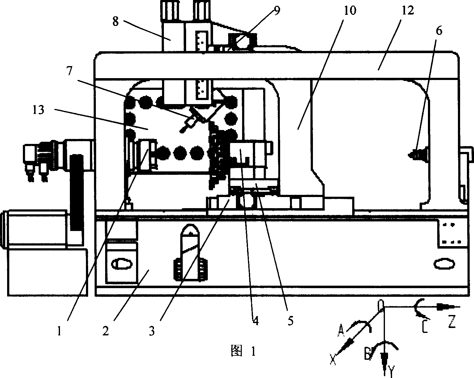
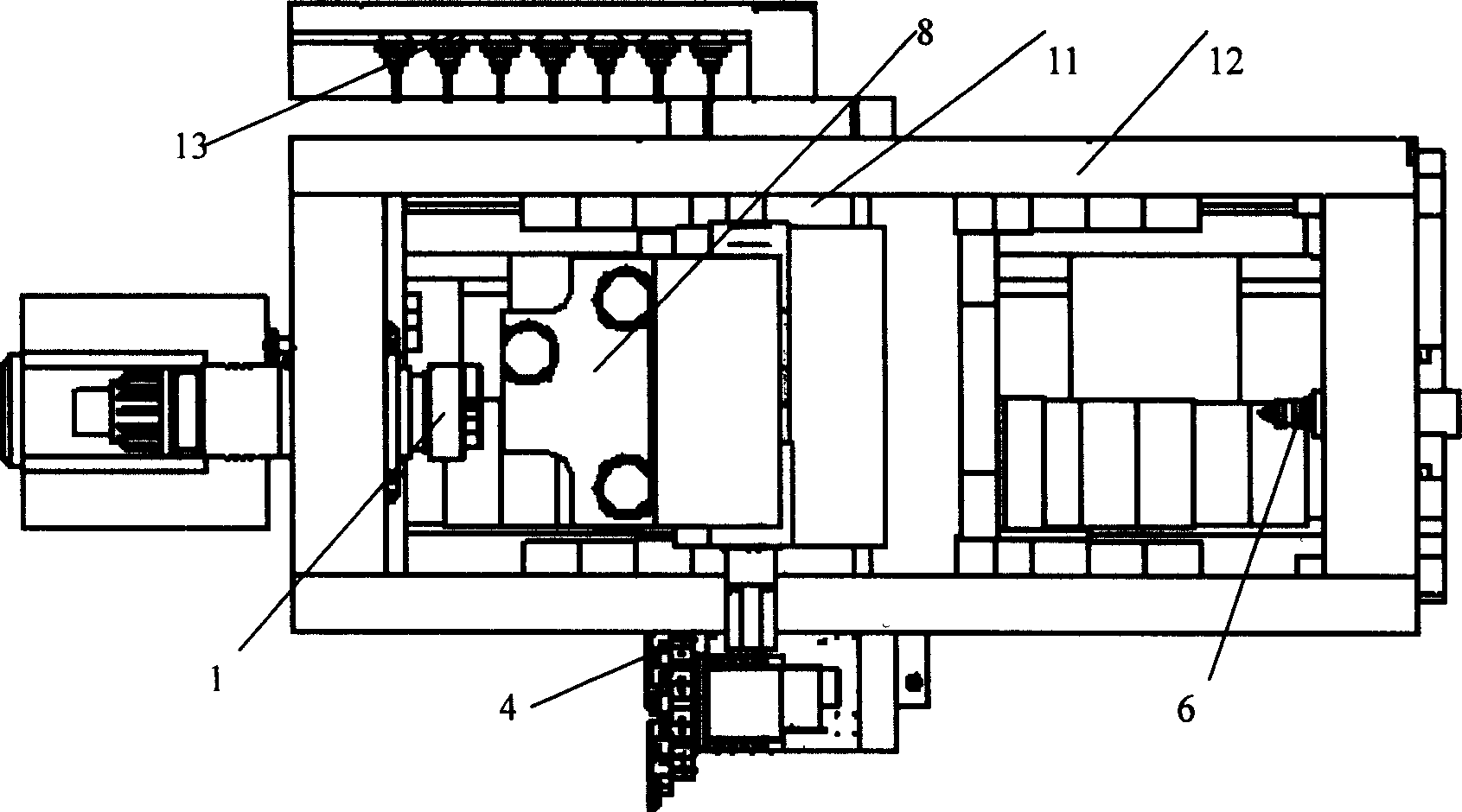
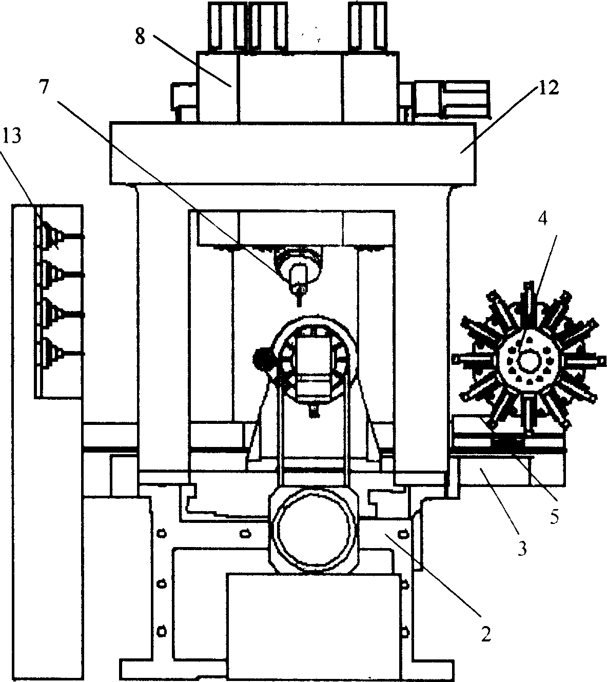
[0020] The motor of the turning spindle head 1 is an AC servo main motor with C-axis function, the spindle head (7) adopts a frequency conversion electric spindle, the tool holder 4 is a turret-type turning tool holder, and the parallel mechanism of the milling tool holder 8 is a 3-PRS mechanism , Each feed motor is a servo motor. The machine tool can realize up to six-axis linkage. The large gantry 12 is installed on the bed 2, and the small gantry 10 is installed on the bed saddle 3, moves longitudinally together with the bed saddle 3, and is connected with the large gantry 12 with guide rails, so that the whole machine tool forms a closed loop circuit structure, rigid high. A standard floor tool magazine is installed on the side of the machine tool.
Embodiment 2
[0022] The difference from Embodiment 1 is that the milling spindle head 7 adopts a servo electric spindle, which adds special slot processing functions, such as inclined slots in different orientations.
PUM
 Abstract
Description
Claims
Application Information