
Vertical polarization single dipole radio station transmitting antenna

A dipole radio, vertical polarization technology, applied in the direction of the antenna array that is energized alone, can solve the problems of reduced radio wave radiation, serious polarization loss, complex antenna structure, etc., to reduce the attenuation of the electromagnetic field and anti-corrosion performance. The effect of strengthening and improving the launch efficiency

Inactive Publication Date: 2004-12-29
江门人民广播电台
View PDF0 Cites 5 Cited by
  • Summary
  • Abstract
  • Description
  • Claims
  • Application Information

AI Technical Summary

Problems solved by technology

If the polarization of the receiving antenna does not match the polarization of the incoming wave, the received power will be lost. When the transmitting antenna is a horizontally polarized wave, if the receiving antenna is a horizontally polarized antenna, the polarization loss will be zero, and the received signal will be the best. Strong, otherwise, there will be a polarization loss, making the received signal weak
[0003] Most of the current FM radio listening tools are portable FM radios, which automatically switch speakers, followed by fixed speaker equipment and vehicle-mounted FM radios. When users receive broadcast signals, they are used to using telescopic antennas inside the machine, and most of the antennas are placed close to vertical. In this way, when receiving horizontally polarized waves, the polarization loss is quite serious
[0004] In order to overcome the problem of poor transmission and reception effect using horizontal polarization, many radio stations have changed the transmitting antenna to vertical polarization, but they generally adopt the method of hanging vibrators on all four sides of the existing iron tower (self-supporting tower or cable tower) , this method requires a large number of oscillators, many matching links, complex structure, and large volume, so the loss is correspondingly large, the cost is high and the effect is not ideal. In addition, it needs to be installed on the existing iron tower, and the existing The height of the iron tower is certain, and the ideal tower section has been installed with antennas, and the addition of transmitting antennas will be limited or the location of the tower section is not ideal, so that the transmission effect is not good, especially today, with the development of radio and television, FM broadcasting in various places The number of TV and broadcast sets has increased compared to before, and the original installation method will inevitably make the contradiction more prominent, which does not meet the needs of development
[0005] There is also a horizontally polarized transmitting antenna installed directly on the ground, which is not limited by the installation position of the tower. It uses a 6-layer batwing antenna, each layer of batwing has 4 vibrators, and a total of 24 vibrators emit horizontal polarization. Wave, this kind of antenna structure is more complicated, there are many interfaces, and it is easy to age and enter the water, causing reflections to cause harm to the transmitter; moreover, the quality of the antenna is heavy and the wind resistance is relatively large, so two layers of climbing wires must be used to fix the antenna support rod body, causing radio waves The amount of radiation is reduced and the gain is reduced

Method used


Image

  • Vertical polarization single dipole radio station transmitting antenna
  • Vertical polarization single dipole radio station transmitting antenna
  • Vertical polarization single dipole radio station transmitting antenna

Examples


Embodiment Construction

[0018] refer to figure 1 , the horizontally polarized transmitting antenna commonly used in radio stations in the prior art can be directly installed on the ground, and a 6-layer batwing antenna is used. Each layer of batwing has 4 vibrators, and a total of 24 vibrators emit horizontally polarized waves. The structure of the antenna is relatively complex, with many interfaces, and it is easy to age and enter the water, causing reflections to cause harm to the transmitter. In addition, the quality of the antenna is heavy and the wind resistance is relatively large. Two layers of climbing wires must be used to fix the antenna support rod body, resulting in a reduction in radio wave radiation. , the gain decreases.

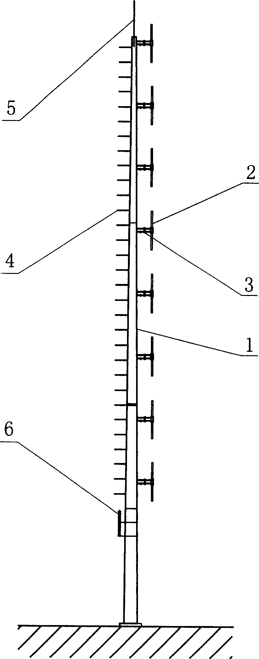
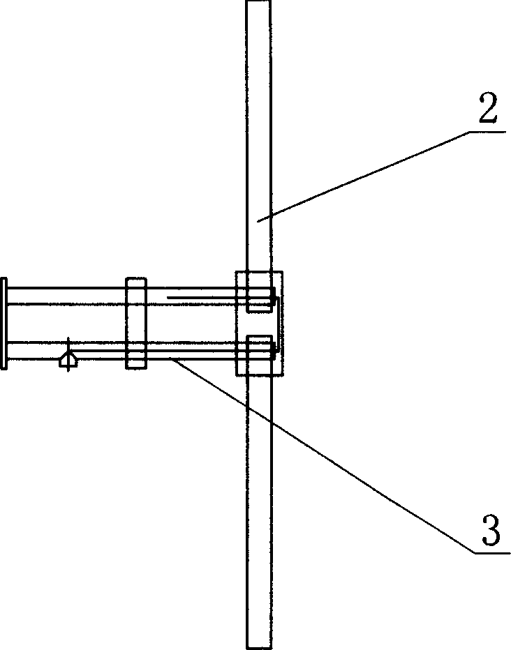
[0019] refer to figure 2 , the vertically polarized single dipole transmitting antenna of the present invention includes a support rod body 1 and a multi-layer antenna vibrator 2 fixedly connected to the rod body, each layer of antenna vibrator is fixedly connected...


PUM


Abstract

The invention discloses a radio station transmitting antenna, especially a transmitting antenna with a perpendicular depolarizing single dipole, comprising a strut body and multilayer antenna vibrators fixed onto the strut body, wherein each layer of the antenna vibrator is a single dipole vibrator, the two poles of which are distributed in a linear form from up to down and perpendicular to the ground, each layer of the antenna vibrator is fixedly connected to the sides of the strut body through stings, the multilayer antenna vibrators are distributed uniformly on the same side of the strut body from up to down, the strut body is a hollow metal pole with a certain taper, and is connected with two sections or more.

Description

technical field [0001] The invention relates to a radio transmitting antenna, in particular to a vertically polarized single dipole transmitting antenna for radio and television stations. Background technique [0002] At present, most radio stations in my country use horizontal polarization to transmit. Due to the excessive and dense horizontal polarization, the same-frequency or adjacent-frequency interference caused by it is becoming more and more serious. Therefore, vertical polarization has emerged to Send out radio waves. Both horizontal polarization and vertical polarization are linear polarization. The orientation of the electric field vector is fixed at any moment in space. The direction of the electric field vector is parallel to the ground for horizontally polarized waves. When the transmitting antenna is rotated 90°, the direction of the electric field vector is the same as The ground is vertical, and at this time, it is a vertically polarized wave. If the polari...

Claims


Application Information

Patent Timeline
Patent Type & Authority Applications(China)
IPC IPC(8): H01Q21/08
Inventor 简励新龙国建李侃游谈栋华
Owner 江门人民广播电台
Learn More