Mixing dynamic gate type machine with electrical driving tires for hoisting ship

A hybrid electric and crane technology, applied in the direction of cranes, trolley cranes, load suspension components, etc., can solve the problems of serious emission pollution, large energy consumption, and insufficient flexibility in steering and driving

Active Publication Date: 2005-01-12
武汉理工通宇新源动力有限公司
View PDF0 Cites 12 Cited by
  • Summary
  • Abstract
  • Description
  • Claims
  • Application Information

AI Technical Summary

Problems solved by technology

Traditional tire gantry cranes usually use diesel engines as the power source, which cons

Method used


Image

  • Mixing dynamic gate type machine with electrical driving tires for hoisting ship
  • Mixing dynamic gate type machine with electrical driving tires for hoisting ship
  • Mixing dynamic gate type machine with electrical driving tires for hoisting ship

Examples


Embodiment Construction

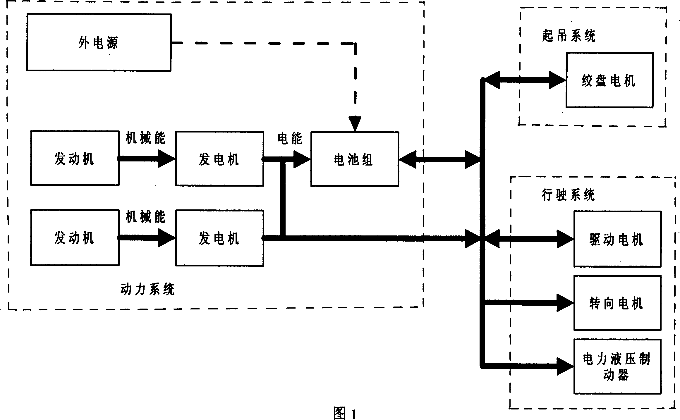
[0021] As shown in Figure 1, the hybrid electric tire gantry crane is mainly composed of a steel structure frame, a lifting system, a power system, a driving system, and a control system. The driving system is composed of a driving system, a braking system, and a steering system. The steel structure frame is the skeleton of the crane, the lifting system is used for the lifting operation of the crane, the hybrid power system provides energy and power for the crane, the drive system assembly enables the crane to realize the self-driving function, and the brake system assembly Realize the form braking function, the steering system assembly realizes the steering function for the crane, there are three steering modes to choose from (such as Figure 8 , Figure 9 , Figure 10 shown), the control system is the control center of the crane.

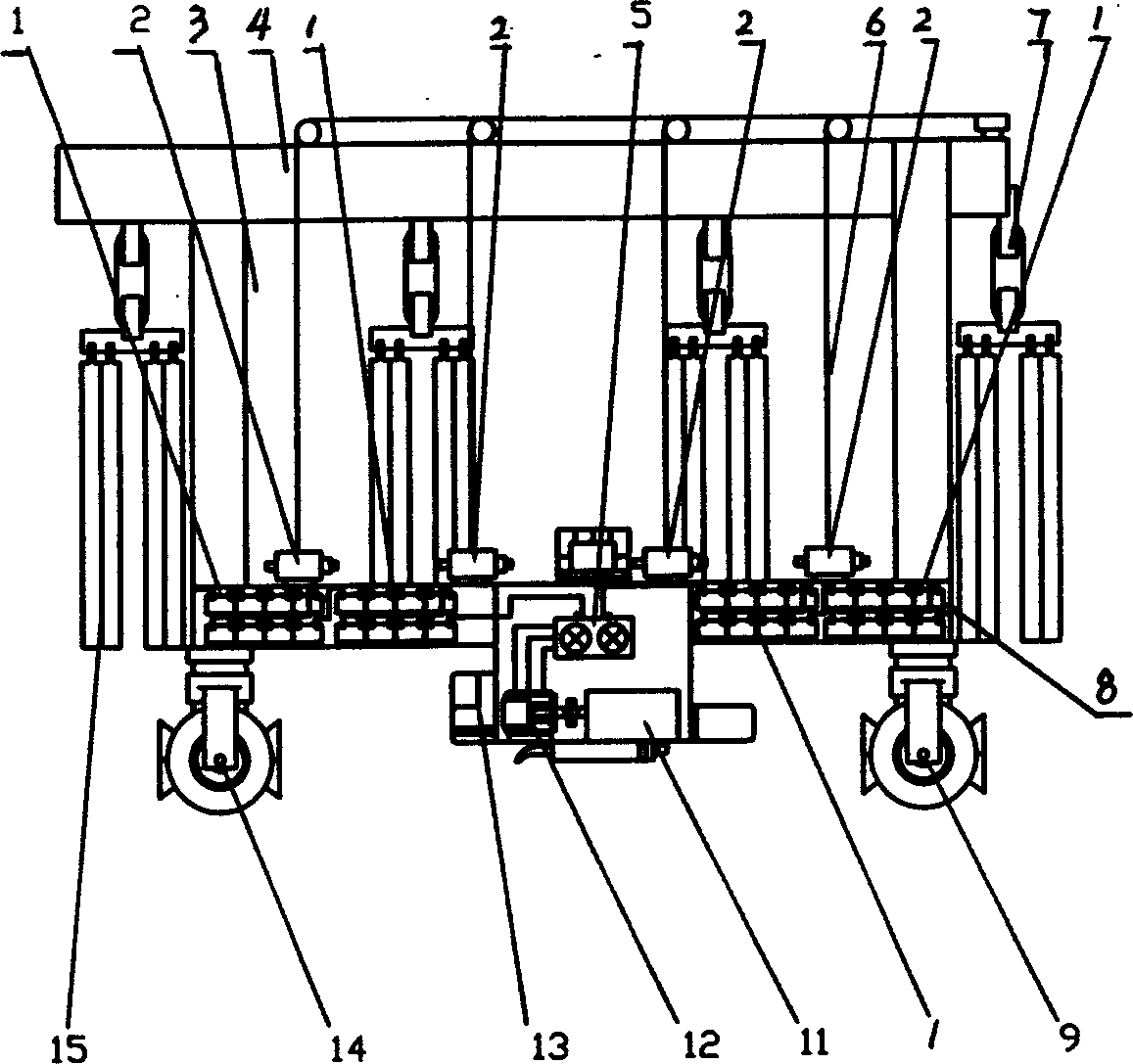
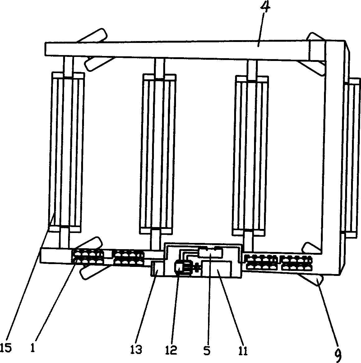
[0022] Such as figure 2 , image 3 , Figure 4 Shown, steel frame is prior art, and steel frame is made of column 3, upper bracket 4, lower ...


PUM


Abstract

An electric gantry ship crane with mixed power system and tyres is composed of structural steel frame, crane system, running system, the power system consisting of engine, electric generator, controller of electric generator, and accumulator set, and the steering system consisting of the vertical volumns of drive wheels, steering motor, steering speed reducing, steering drive gear, steering axle and thrust roller bearings.

Description

technical field [0001] The invention belongs to a large tire hoisting and carrying machine, which is used for hoisting operations of small ships. Background technique [0002] Tire lifting and carrying equipment has been applied in ports and other workplaces, such as port tire cranes, tire container gantry cranes and so on. Traditional tire gantry cranes usually use diesel engines as the power source, which consumes a lot of energy and emits serious pollution; and the steering is not flexible enough. Contents of the invention [0003] The object of the present invention is to provide a kind of hybrid electric tire gantry crane with hybrid power and flexible steering. [0004] In order to achieve the above object, the technical solution of the present invention is: a hybrid electric tire gantry crane, which includes a steel structure frame, a lifting system, a power system, and a driving system, and the driving system is composed of a driving system, a braking system, and ...

Claims


Application Information

Patent Timeline
IPC IPC(8): B66C13/12B66C19/00
Inventor 吴森金德先林枫王琛段海涛
Owner 武汉理工通宇新源动力有限公司
Why Eureka
Try Eureka