
Time delayed testing generation method for wire-to-wire crosstalk decereration effect

A technology of time-delay test and deceleration effect, applied in semiconductor/solid-state device test/measurement, electrical components, electro-solid-state devices, etc., it can solve the problems of large number of faults, difficult to find tests, long calculation time, etc.

Active Publication Date: 2005-01-12
INST OF COMPUTING TECH CHINESE ACAD OF SCI
View PDF0 Cites 0 Cited by
  • Summary
  • Abstract
  • Description
  • Claims
  • Application Information

AI Technical Summary

Problems solved by technology

The disadvantages are: the number of faults is large; due to the short-path effect of the gate delay test, it is difficult to find the worst-case test; the test generation algorithm requires a large change in the traditional algorithm
The disadvantages are: it is impossible to generate tests for suspected crosstalk sources in a targeted manner; genetic algorithms and SPICE (The Stanford Program on International and Cross-Cultural Education, a general-purpose circuit-level simulation program first developed by Stanford University in the United States, and later adopted by the industry The combination of universally adopted and extended) simulations introduces multiple iterations of SPICE simulations, which require a long calculation time

Method used


Image

  • Time delayed testing generation method for wire-to-wire crosstalk decereration effect

Examples


Embodiment Construction

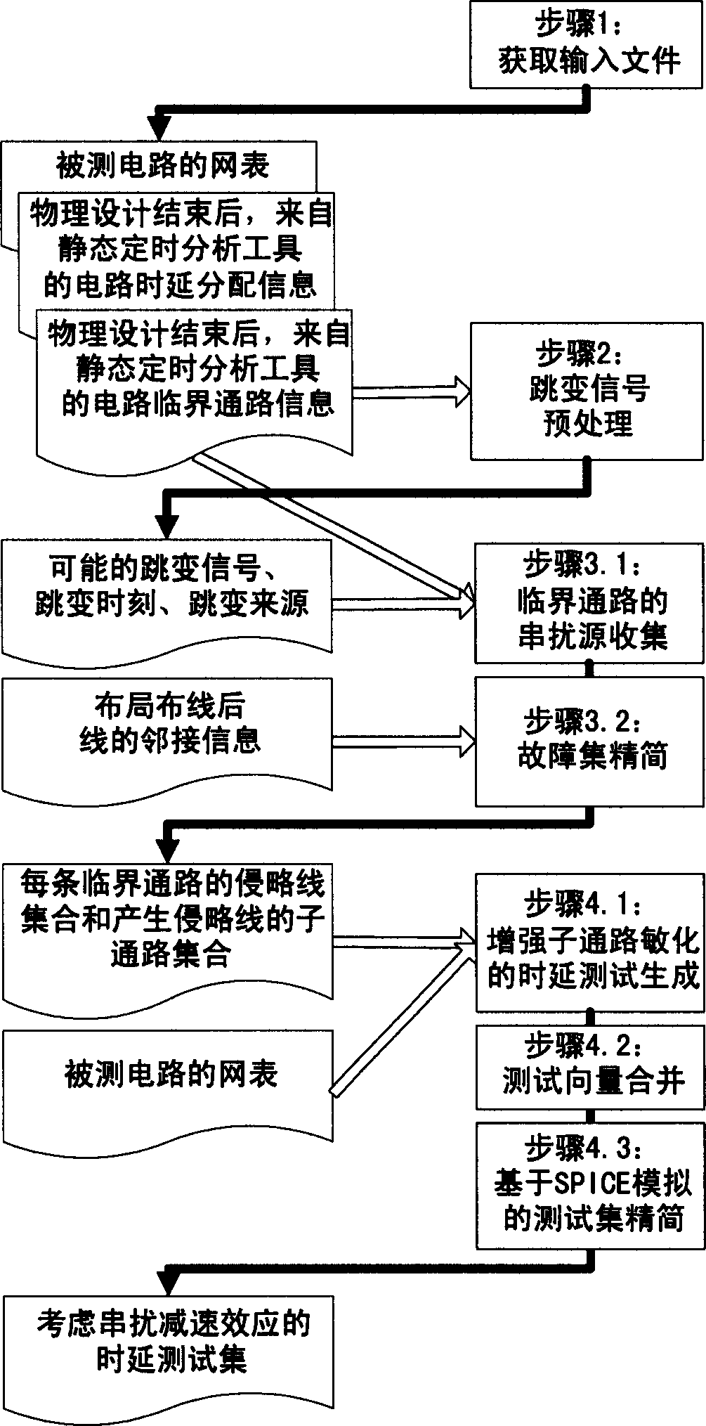
[0037] figure 1 The rectangular block diagram in the middle right half shows the main steps to realize the method, figure 1 The file block diagram in the middle left half shows the output files and input files of each step. figure 1 The solid black arrows in indicate "file output", and the hollow arrows indicate "file input".

[0038] figure 1 In the prototype system of the time delay test generation method for crosstalk deceleration effect between lines, the 4 steps introduced in the technical solution of the invention are included. Except that SPICE simulation adopts off-the-shelf commercial tools, we have implemented tool prototypes in C language for other parts, which can test and generate benchmark circuit netlists in the research field.

[0039] We use figure 1 The system is tested on the reference circuit netlist ISCAS89 in the research field (the reference circuit proposed by the International Conference on Circuits and Systems in 1989). Due to the lack of real phy...


PUM


Abstract

The method includes steps: collecting source of cross talk between lines; selecting faults and reducing fault set; carrying out time delay test generation for reduced fault set. Specific test of time delay is needed to carry out for degressive performance caused by retardation effect of cross talk between lines. The steps are as following: (1) obtaining circuit delay assignment and critical path; (2) preprocessing jump signal; (3) collecting source of cross talk in critical path; (4) enhancing sub path sensitized time delay test generation and reduction of testing set.

Description

technical field [0001] The invention relates to the technical field of semiconductor technology, in particular to a delay test generation method for crosstalk deceleration effect between lines, which is to generate time delay test for the performance degradation caused by crosstalk deceleration effect between lines, effectively simplifying fault sets, and improving test performance. Latency test generation method for generation efficiency and reduced test cost. Background technique [0002] The increasingly refined semiconductor technology makes the transistor size smaller and smaller, so the signal transition edge of the device is faster and faster, which leads to increasingly serious signal integrity problems in the field of high-speed digital circuit system design. Signal integrity refers to the quality of the signal on the signal line. A signal with good signal integrity means that it has the necessary voltage levels to reach when needed. Signal integrity issues are no...

Claims


Application Information

Patent Timeline
IPC IPC(8): H01L21/02H01L21/66H01L21/70H01L21/768
CPCH01L2924/0002
Inventor 李华伟李晓维
Owner INST OF COMPUTING TECH CHINESE ACAD OF SCI
Learn More