Smallest voltage active clamped single-phase A.C-D.C power factor correction transformer

A single-phase AC and DC power technology, applied in the direction of converting irreversible DC power input into AC power output, output power conversion device, high-efficiency power electronic conversion, etc., can solve the problems of large switching loss of devices and lower circuit efficiency , to achieve the effect of increasing power density, improving circuit efficiency and reducing switching loss

Inactive Publication Date: 2005-01-12
ZHEJIANG UNIV
View PDF0 Cites 1 Cited by
  • Summary
  • Abstract
  • Description
  • Claims
  • Application Information

AI Technical Summary

Problems solved by technology

This single-phase AC-DC power factor correction converter is applied to the global universal power input and can realize power factor correction, but the circuit works in a hard switching state, and there is a reverse recovery problem of the diode, and the switching loss of the device is large, which limits the work. frequency increases, reducing circuit efficiency

Method used


Image

  • Smallest voltage active clamped single-phase A.C-D.C power factor correction transformer
  • Smallest voltage active clamped single-phase A.C-D.C power factor correction transformer
  • Smallest voltage active clamped single-phase A.C-D.C power factor correction transformer

Examples


Embodiment Construction

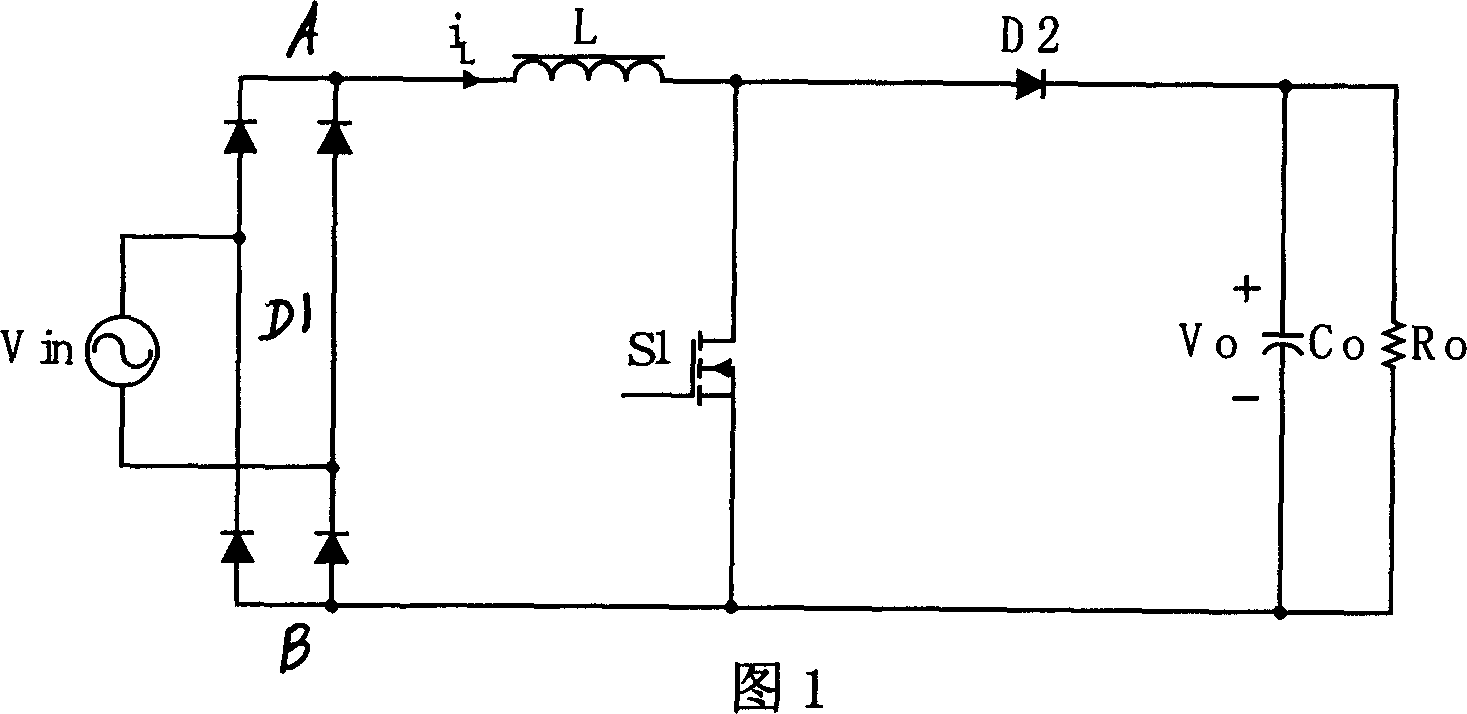
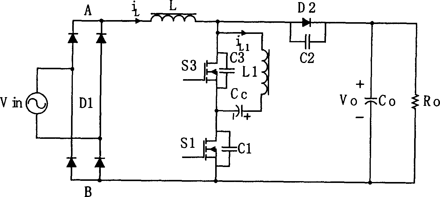
[0011] refer to figure 2 , the minimum voltage active clamp single-phase AC-DC power factor correction converter of the present invention comprises the rectification circuit D1 that is made of four diodes, inductance L, diode D2 and main switch S1, one end of inductance L and the output of rectification circuit The terminal A is connected, the other end is connected with the positive terminal of the diode D2, and the series circuit of the main switch S1 and the auxiliary switch S3 is connected between the junction of the inductor L and the diode D2 and the other output terminal B of the rectifier circuit, and the auxiliary switch S3 The two ends of the diode D2 are connected in parallel with the third capacitor C3 and a circuit connected in series across the resonant inductor L1 and the clamping capacitor Cc, and the output capacitor Co is connected between the negative terminal of the diode D2 and the other output terminal B of the rectifier circuit.

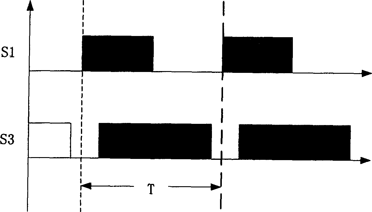
[0012] The following co...


PUM


Abstract

The converter includes rectification circuit, inductance, diode and main switch. One end of inductance is connected to output end of rectification circuit, and the other end of inductance is connected positive end of the diode. Cascaded circuit of main switch and resonant inductance is connected between connection point of inductance and diode and another output end of rectification circuit. Cascaded circuit of resonant inductance and clamping capacitance is cross connected on two ends of resonant inductance. Two ends of the said auxiliary switch are connected to third capacitance etc. Output capacitance is connected between negative diode and other output end of the rectification circuit. Features are: simple structure, restraining backward recovery of diode connected in inverted parallel, realization of soft switch and high efficiency of circuit. The converter is applicable to preceding stage of rectifier unit in distribution power source/

Description

[0001] technology field or [0002] The invention relates to a power factor correction converter, especially a soft-switching single-phase AC-DC power factor correction converter. Background technique [0003] The current single-phase AC-DC power factor correction converter is shown in Figure 1, which includes a rectifier circuit composed of four diodes, an inductor L, a diode D2 and a main switch S1, and one end of the inductor L is connected to the output end of the rectifier circuit , the other end is connected to the positive end of the diode D2, the main switch S1 branch is connected between the junction of the inductor L and the diode D2 and the other output end of the rectification circuit, and the negative end of the diode D2 is connected to the other output end of the rectification circuit Indirect output capacitor Co. This single-phase AC-DC power factor correction converter is applied to the global universal power input, and can realize power factor correction, but...

Claims


Application Information

Patent Timeline
Patent Type & Authority Applications(China)
IPC IPC(8): H02M1/14H02M7/48
CPCY02B70/1491Y02B70/10Y02P80/10
Inventor 徐德鸿冯波徐君
Owner ZHEJIANG UNIV
Why Eureka
Try Eureka