
Method and arrangement for limiting signal in radio transmitter

A technology for limiting signals and transmitters, applied in electrical components, modulated carrier systems, digital transmission systems, etc., can solve problems such as inability to apply multi-carrier systems, user interference, etc., and achieve the effect of saving transmission power consumption and improving performance.

Inactive Publication Date: 2005-01-12
NOKIA NETWORKS OY
View PDF0 Cites 0 Cited by
  • Summary
  • Abstract
  • Description
  • Claims
  • Application Information

AI Technical Summary

Problems solved by technology

However, the limitation method has the disadvantage that the spectrum of the signal is usually extended, which extends beyond the assigned frequency band and thus causes interference to other users
The disadvantage of the limiting method is that it can only limit one signal at a time, so it is not suitable for multi-carrier systems

Method used


Image

  • Method and arrangement for limiting signal in radio transmitter
  • Method and arrangement for limiting signal in radio transmitter
  • Method and arrangement for limiting signal in radio transmitter

Examples


Embodiment Construction

[0022] The technical solution of the present invention is especially suitable for WCDMA (Wideband Code Division Multiple Access) radio system using Direct Sequence (DS) technology. Other applications include, for example, satellite systems, military telecommunications systems, and private non-cellular networks. But the technical solution of the present invention is not limited thereto.

[0023] In the following examples, preferred embodiments of the invention are described within the UMTS system (Universal Mobile Telephone System), but the invention is not limited thereto.

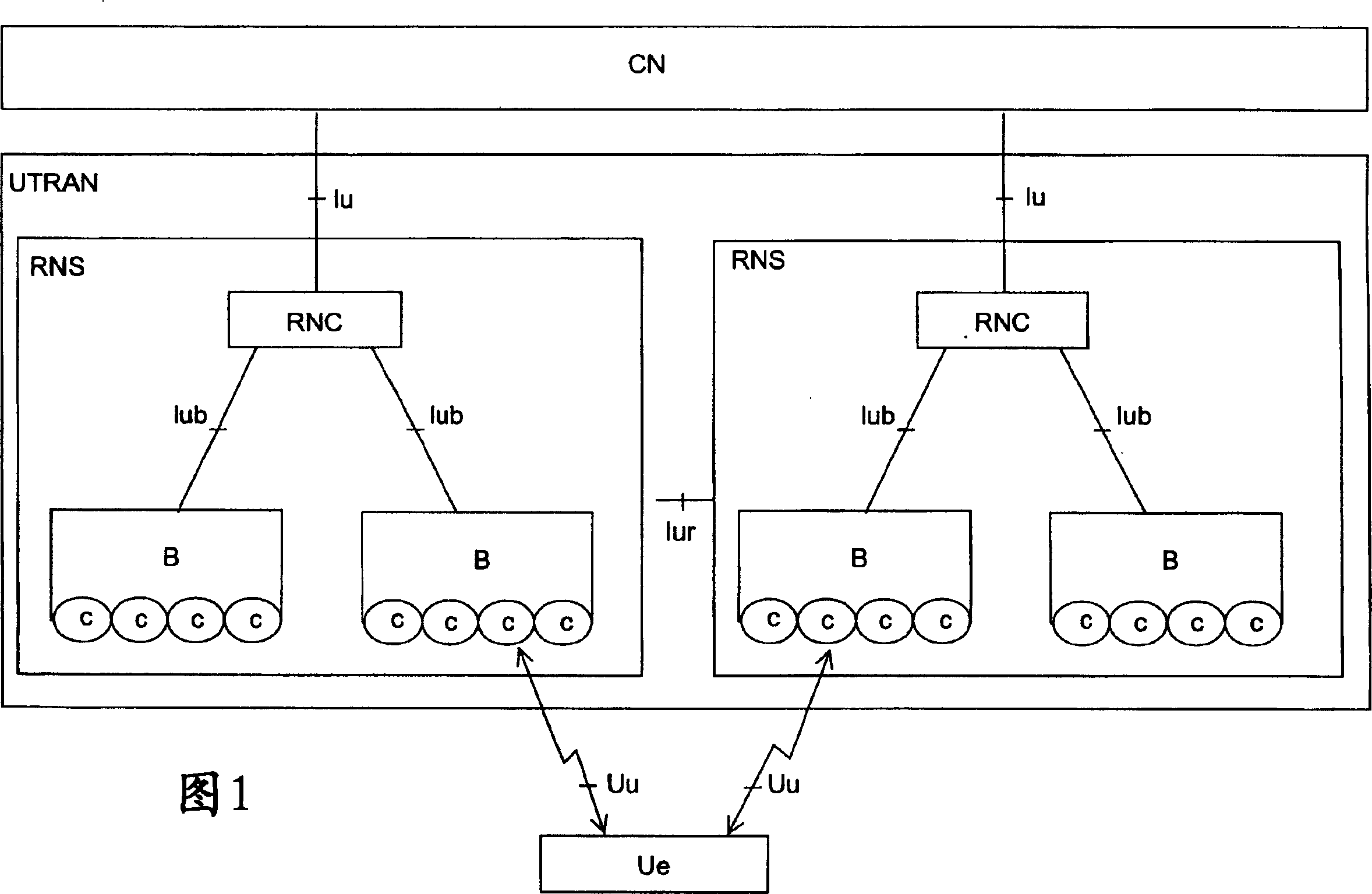
[0024] Referring to Fig. 1, the structure of a mobile phone system is described by way of example. The main parts of the mobile telephone system comprise a core network CN, a UMTS terrestrial radio access network UTRAN and user equipment Ue. The interface between CN and UTRAN is called Iu, and the air interface between UTRAN and Ue is called Uu.

[0025] UTRAN includes the Radio Network Subsystem RNS. ...


PUM


Abstract

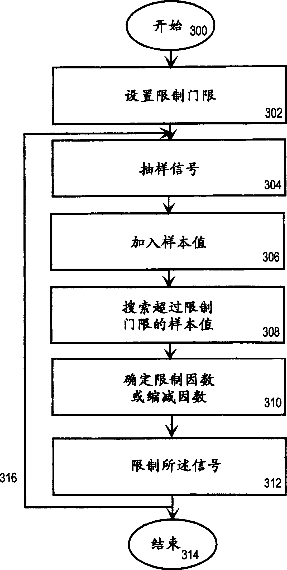
A method for limiting a signal in a radio transmitter, comprising giving (302) a limiting threshold to a signal, taking (304) at least two samples from said signal to obtain sample values, in the obtained first sample Adding (306) one or more sample values ​​between this value and at least one subsequent sample value, searching (308) for sample values ​​exceeding said limit threshold, and if at least one sample value exceeding said limit threshold is found, then A limiting factor or reduction factor is determined (310) for a predetermined number of sample values ​​by means of said at least one sample value exceeding said limiting threshold, and said signal is limited (312) by one or more of the determined factors.

Description

technical field [0001] The invention relates to a method and a device for limiting the power level and amplitude of a signal in a radio transmitter. Background technique [0002] In several data transmission systems, the linearity of the power amplifier limits the maximum achievable transmit power, especially when the transmitted signal has a high peak-to-average ratio. Therefore, a signal applied to a power amplifier may momentarily exhibit a higher power value or amplitude, which should be taken into account when designing the power amplifier. In practice, this means that the amplifier input signal is scaled to a lower power or amplitude level to meet the spectral requirements of the data transmission system being used. This method, known as compensation, provides for localizing the amplified signal in the region where the transfer function of the amplifier is more linear. However, the problem is that the compensation degrades the performance of the amplifier and / or tran...

Claims


Application Information

Patent Timeline
Patent Type & Authority Applications(China)
IPC IPC(8): H04B1/707H04L27/26H04L27/36
CPCH04B1/70755H04B2201/70706H04L27/2624H04L27/366
Inventor 托皮欧·奥帕拉奥利·皮赖宁
Owner NOKIA NETWORKS OY
Learn More