Burner for synthesis gas

A technology of burners and combustion chambers, which is applied in the direction of gas fuel burners, burners, combustion chambers, etc., and can solve the problems of inability to maintain effective injection of natural gas, high backfire risk, etc.

Inactive Publication Date: 2005-01-26
GENERAL ELECTRIC TECH GMBH
View PDF7 Cites 4 Cited by
  • Summary
  • Abstract
  • Description
  • Claims
  • Application Information

AI Technical Summary

Problems solved by technology

[0009] In the case of synthesis gas combustion, it would not be possible to maintain an effective injection of natural gas on prior art burners due to the high risk of flashback

Method used


Image

  • Burner for synthesis gas
  • Burner for synthesis gas
  • Burner for synthesis gas

Examples


Embodiment Construction

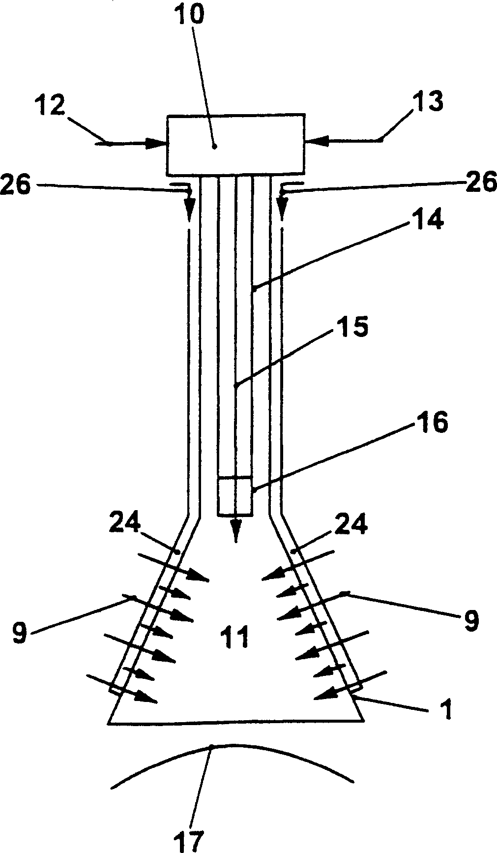
[0033] figure 1 A premix burner is shown very schematically, such as is known from EP 321 809 A1. The burner consists of a burner head 10 and a swirl generator 1 connected thereto, which forms a swirl space 11 . In such a burner, the conical swirl generator 1 consists of a plurality of burner shells, between which tangential inlet slots for the combustion air 9 are formed. The incoming combustion air 9 is indicated in the figure by a long arrow. Furthermore, a gas supply 24 can be provided along the tangential inlet grooves for feeding fuel, in particular natural gas 26, into the swirl space 11 via the tangential air inlet grooves. This fuel or natural gas is indicated in the figure by a short arrow. From the burner head 10 a burner nozzle 14 projects, which extends into the swirl space 11 and is provided at its end with a nozzle 16 for injecting a liquid fuel 13 , for example oil and / or water 12 . In particular, burner ignition will take place via the burner nozzle 14 . ...


PUM


Abstract

The invention relates to a burner which essentially consists of a swirl generator (1) for a combustion air flow, and means for introducing fuel into said combustion air flow (9). Said swirl generator (1) comprises combustion air inlets for the combustion air flow (9) entering the burner, and the means for introducing fuel into the combustion air flow (9) comprise at least one first fuel admission (19) and a group of first fuel outlets (18) which are arranged in a distributed manner on an end of the burner on the side of the combustion chamber, about the burner axis (25). Said burner is characterised in that the at least one fuel admission (19) and the group of first fuel outlets (18) are mechanically decoupled from the swirl generator (1). The inventive burner enables synthesis gas to be used in a reliable and safe manner, both in a rarefied and in a non-rarefied form.

Description

technical field [0001] The invention relates to a burner operating in a combustion space, preferably in the combustion chamber of a gas turbine, essentially consisting of a swirl generator for the combustion air flow and means for injecting fuel into the combustion air flow, wherein the vortex The swirl generator has a combustion air inlet for the combustion air flow entering the burner and the means for injecting fuel into the combustion air flow includes one or more fuel supply sections with a set of first fuel outlet holes, the fuel outlet holes They are arranged distributed around the burner axis at the combustion chamber-side end of the burner. [0002] A preferred field of application for such burners is gas and steam turbine technology. Background technique [0003] From EP 0 321 809 B1, according to the preamble of claim 1 , a conical burner consisting of several shells, a so-called double cone burner, is known. A conical vortex generator consisting of several shel...

Claims


Application Information

Patent Timeline
Patent Type & Authority Applications(China)
IPC IPC(8): F23R3/28F02C7/00F02C7/232F02C9/26F23C7/00F23C99/00F23D11/40F23D14/02F23D17/00F23R3/00F23R3/12
CPCF23D11/402F23D17/002F23C7/002F23C2900/07002F23R3/36F23R2900/00002
Inventor 蒂莫西·格里芬阿尔贝特·凯勒约阿希姆·克劳齐格罗兰·米克芙兰克·赖斯
Owner GENERAL ELECTRIC TECH GMBH
Why Eureka
Try Eureka