Non round gear and volumetric flowmeter using same

A technology of non-circular gears and flowmeters, which is applied in liquid/fluid solid measurement, measurement flow/mass flow, measurement devices, etc., and can solve the problems of undurable, short-sealed gears, etc.

Inactive Publication Date: 2005-02-02
OVAL CORP
View PDF2 Cites 12 Cited by
  • Summary
  • Abstract
  • Description
  • Claims
  • Application Information

AI Technical Summary

Problems solved by technology

[0012] In addition, not only resin-molded non-circular gears, but even non-circular gears made of metal, for example, ha

Method used


Image

  • Non round gear and volumetric flowmeter using same
  • Non round gear and volumetric flowmeter using same
  • Non round gear and volumetric flowmeter using same

Examples


Embodiment Construction

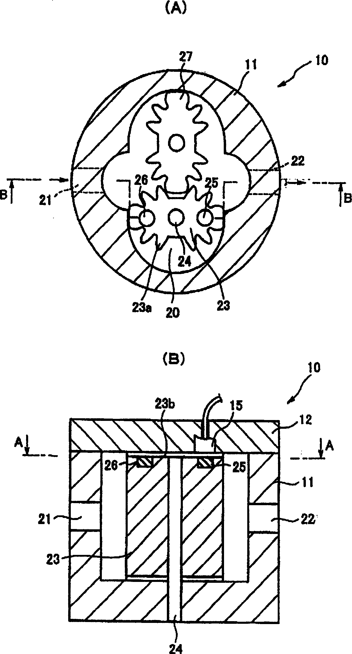
[0033] figure 1 It is a diagram showing a configuration example of a positive displacement flowmeter having a non-circular gear according to an embodiment of the present invention, figure 1 (A) is figure 1 (B) A-A line view sectional view, figure 1 (B) is figure 1 (A) B-B line view section view. In the figure, symbol 10 is a positive displacement flowmeter, symbol 11 is a casing (outer basket), symbol 12 is an end plate, symbol 15 is a magnetic sensor, symbol 20 is a measuring chamber, symbol 21 is an inlet, and symbol 22 is an outlet. , Symbols 23 and 27 are rotors, symbol 23a is the gear part (engagement part) of the rotor 23, symbol 23b is the end surface of the rotor 23, symbol 24 is the rotating shaft of the rotor 23, and symbols 25 and 26 are magnets.

[0034] The main components of the positive displacement flowmeter 10 are: the outer basket 11, the cover (end panel) 12, and the measuring chamber 20 corresponding to the space formed by the outer basket 11 and the end ...


PUM


Abstract

The number of teeth is set to 4n+2 (n is a natural number), both the ends on a long axis are set to be teeth grooves, both the ends on a short axis are set to be tips, a pitch curve is set to be, for example, an ellipse, and tooth marks 31-37, 41-47 are set to be basic tooth mark curves. With the tooth mark curve, the engagement teeth surface is set to be an involute curve, a non-engagement tooth surface is set to be a cycloid curve, and the tool pressure angle of each tooth mark is set by an undercut limit and a point limit. The non-circular gears 30, 50 bury the recess between two tooth marks, holding the tooth space located at both the ends on the long axis, based on the basic tooth mark curve, and have a shape, where the tooth section including the tip at both the ends on the short axis are scraped off, and the number of teeth completed is finally set to 4n-2. Accordingly, it is able to obtain a non-circular gear that reduces the change in an engagement pressure angle, is advantageous for setting the tool pressure angle of an engagement teeth surface, can reduce the number of teeth without forming an overhang section, and can fully secure the sealing performance with the inner wall of a casing to be installed.

Description

technical field [0001] The present invention relates to non-circular gears and positive displacement flowmeters using non-circular gears. Background technique [0002] Non-circular gears have traditionally been used in positive displacement flow meters and pumps, among other things. Among the non-circular gears, the (gear) pitch line is represented by ρ=a / (1-bcos2θ), the meshing pressure angle changes greatly due to the rotation, and in order to avoid the undercutting of the tooth profile of the long diameter part The interference of etc. reduces the modulus of the tooth shape, so that the number of teeth increases. The ρ mentioned here is the vector radius, a is the similarity coefficient, b is the flatness, and θ is the deflection angle. [0003] An elliptical gear, which is a type of elliptical gear, has been proposed as a technology that does not increase the change in the meshing pressure angle due to rotation (for example, refer to Japanese Patent Publication No. 1-3...

Claims


Application Information

Patent Timeline
IPC IPC(8): G01F3/10F03C2/08F04C2/18
Inventor 小野精悟
Owner OVAL CORP
Why Eureka
Try Eureka