
Nonvolatile semiconductor memory device and control method thereof

A non-volatile, storage device technology, applied in the field of memory arrays of storage cells, can solve the problems of large dispersion of variable resistance elements, increased power consumption, etc.

Active Publication Date: 2005-02-02
SAMSUNG ELECTRONICS CO LTD
View PDF0 Cites 31 Cited by
  • Summary
  • Abstract
  • Description
  • Claims
  • Application Information

AI Technical Summary

Problems solved by technology

That is, if there is a gap in the writing threshold voltage changing from the low resistance state (hereinafter referred to as RL) to the high resistance state (hereinafter referred to as RH) of the variable resistance element, or the erasing threshold voltage changing from the high resistance state to the low resistance state, When the same voltage is applied to the variable resistance element for writing or erasing, there will be a very large dispersion in the amount of current flowing through the variable resistance element, and the power consumption during writing or erasing will increase. Big

Method used


Image

  • Nonvolatile semiconductor memory device and control method thereof
  • Nonvolatile semiconductor memory device and control method thereof
  • Nonvolatile semiconductor memory device and control method thereof

Examples


Embodiment approach 1

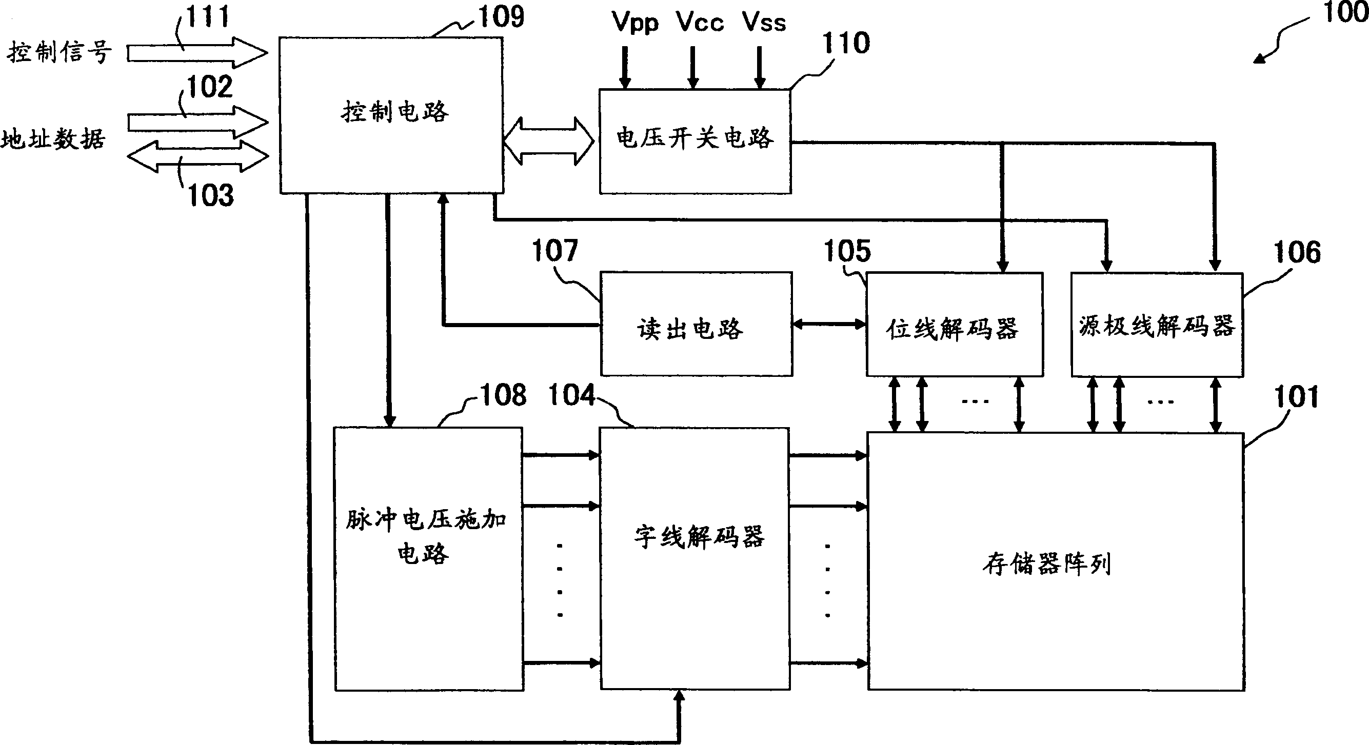
[0040] figure 1 A block diagram of an apparatus 100 of the present invention is shown. The device 100 of the present invention stores information in the memory array 101, and the memory array 101 adopts a structure configured with a plurality of storage units, and can store and read information in the storage units in the memory array 101.

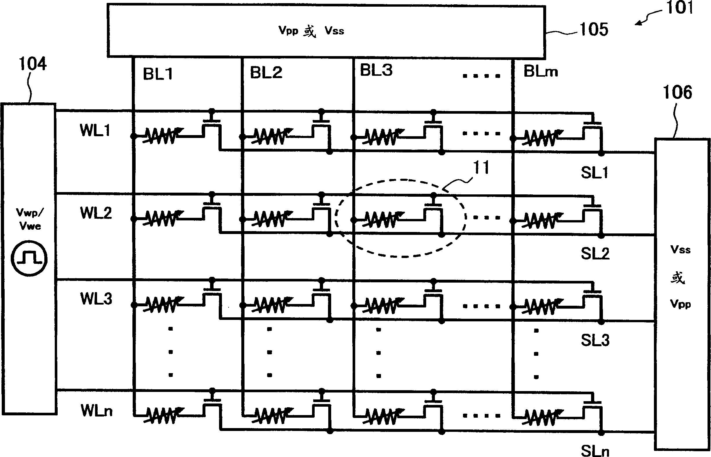
[0041] Information is stored in a specific memory cell in the memory array 101 corresponding to an address input from the address line 102 , and the information is output to an external device through the data line 103 . The word line decoder 104 selects the word line of the memory array 101 corresponding to the signal input to the address line 102, the bit line decoder 105 selects the bit line of the memory array 101 corresponding to the address signal input to the address line 102, and the source The line decoder 106 selects the source line of the memory array 101 corresponding to the address signal input to the address line 102 . The...

Embodiment approach 2

[0087] In the device of the present invention and the method of the present invention according to Embodiment 1, the amplitudes Vwp and Vwe of the pulse voltage applied to the gate electrode 5 of the selection transistor 6 of the memory cell 11 are independently adjusted for writing and erasing. Write and delete operations are explained. In Embodiment 1, the period during which the memory cell 11 is in the write or erase operation state is defined according to the pulse width of the pulse voltage applied to the gate electrode 5 . On the other hand, in the device of the present invention and the method of the present invention according to the second embodiment, a pulse voltage is applied to either the bit line or the source line connected to the memory cell to be written or erased. The programming voltage or erasing voltage between the bit line and the source line is applied in a pulse form, during which a predetermined word line voltage is applied to the word line connected t...

other Embodiment approach

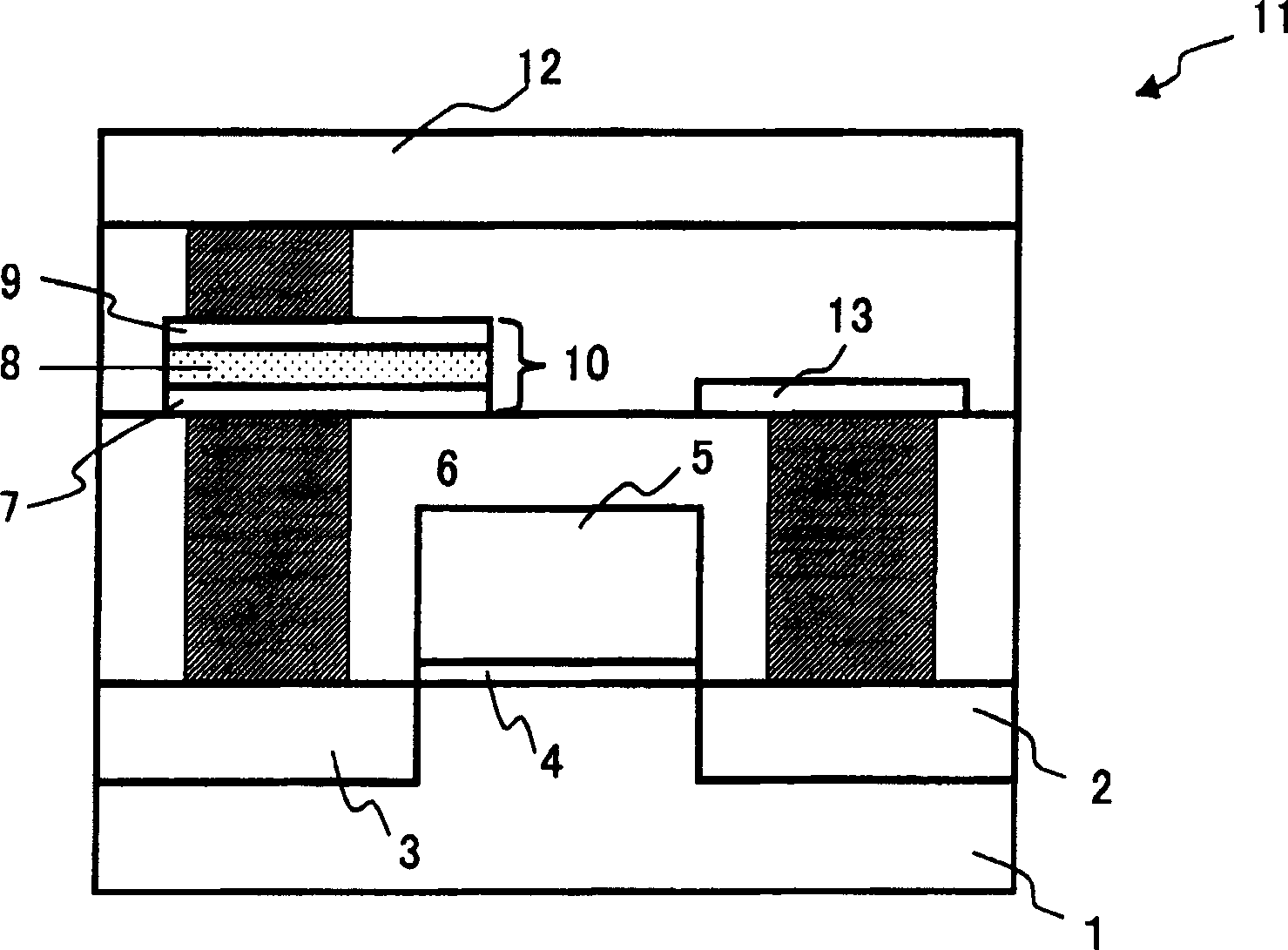
[0099] In each of the above-mentioned embodiments, the storage unit 11 is figure 2 and Figure 7 shown in the figure, but the memory cell 11 may also be configured as follows: the source region 2 of the selection transistor 6 is electrically connected to the lower electrode 7 of the variable resistance element 10, the upper electrode 9 is connected to the source line, and the drain region 3 is connected to the bit line to alternate the arrangement of the selection transistor 6 and the variable resistance element 10. By alternation of this arrangement, the voltage difference (Vpp-Vss) between the upper electrode 9 and the drain region 3 is divided into the voltage Vr across the variable resistive element 10 and the source-drain voltage Vds. under normal conditions with figure 2 and Figure 7 The memory cells shown are constructed identically.

[0100] In addition, the device of the present invention and the method of the present invention are not limited to the above-ment...


PUM


Abstract

A nonvolatile semiconductor memory device includes a memory array (101) in which a plurality of memory cells are arranged in a row direction and a column direction, each of the memory cells being formed by connecting one end of a variable resistive element for storing information according to a change in electric resistance caused by an electric stress and a drain of a selection transistor to each other on a semiconductor substrate, a voltage switch circuit (110) for switching among a program voltage, an erase voltage and a read voltage to be applied to the source line and the bit line connected to the memory cell, and a pulse voltage applying circuit (108). In the state where the program voltage or erase voltage corresponding to the bit line and the source line is applied to the bit line and the source line connected to a memory cell to be programmed or erased in the memory array via the voltage switch circuit (110), the pulse voltage applying circuit (108) applies a voltage pulse for programming or erasing to the word line connected to the gate electrode of the selection.

Description

technical field [0001] The present invention relates to a memory having a plurality of memory cells formed by connecting one end of a variable resistance element for storing information based on a change in resistance of a voltage application and a drain of a selection transistor, respectively arranged in a row direction and a column direction on a semiconductor substrate. An arrayed nonvolatile semiconductor memory device and a control method thereof, specifically, relate to a method of applying voltage to memory cells when writing or erasing. Background technique [0002] In recent years, we are entering an era where information can be obtained anytime, anywhere and freely carried. With the popularization of mobile devices represented by mobile phones and PDAs (portable information communication devices for personal use), various information can be accessed anytime and anywhere. However, the performance of mobile devices, such as battery life and access speed to informati...

Claims


Application Information

Patent Timeline
Patent Type & Authority Applications(China)
IPC IPC(8): G11C16/14G11C11/56G11C13/00G11C16/02G11C16/10G11C16/12H01L27/10H01L45/00
CPCG11C13/0069G11C11/5685G11C2213/79G11C2213/31G11C13/0007G11C2013/009G11C2013/0071G11C13/0064G11C5/063
Inventor 森本英德
Owner SAMSUNG ELECTRONICS CO LTD
Learn More