Brush holder device for dynamoelectric machine

A technology for electric motors and brush holders, which is applied in the direction of electromechanical devices, electric components, and control of mechanical energy, and can solve problems such as difficult cover and reliable insulation of terminal parts

Active Publication Date: 2005-02-02
DENSO CORP
View PDF3 Cites 15 Cited by
  • Summary
  • Abstract
  • Description
  • Claims
  • Application Information

AI Technical Summary

Problems solved by technology

However, since the terminals of the circuit breaker are kept close to each other, the terminals of the substrate connected to the terminals of the circuit breaker overlap with the circuit breaker, which makes it difficult to achieve reliable insulation between the cover and the terminal parts

Method used


Image

  • Brush holder device for dynamoelectric machine
  • Brush holder device for dynamoelectric machine
  • Brush holder device for dynamoelectric machine

Examples


Embodiment Construction

[0043] Embodiments of the present invention will be described below with reference to the drawings.

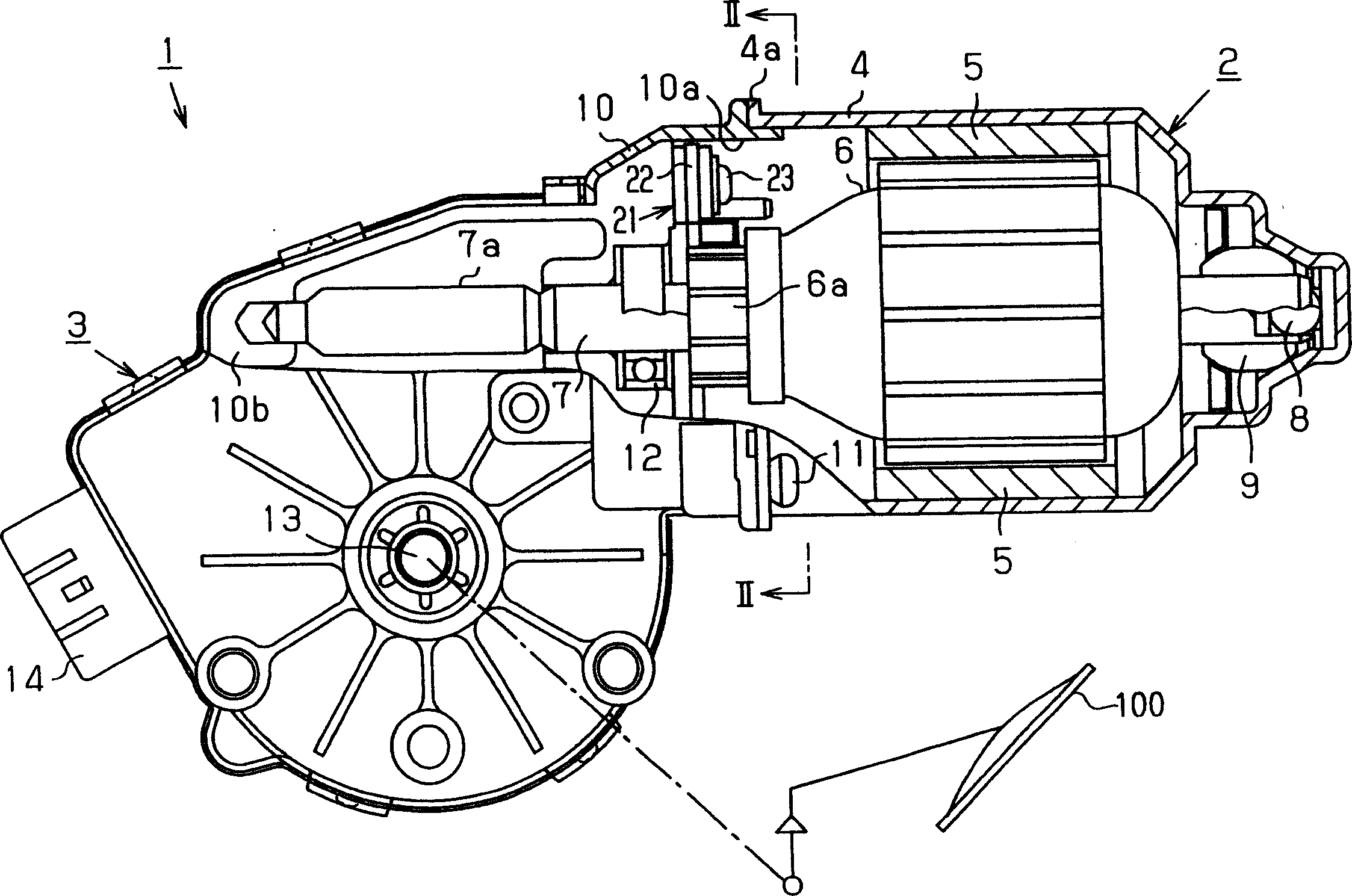
[0044] figure 1 The wiper motor (electric machine) 1 shown in is used as a drive source for the vehicle wiper system by using the wiper 100 (only in figure 1 One is shown in ) Wipe off the raindrops adhering to the windshield (front glass). The wiper motor 1 includes a motor unit 2 and a reduction unit 3 .

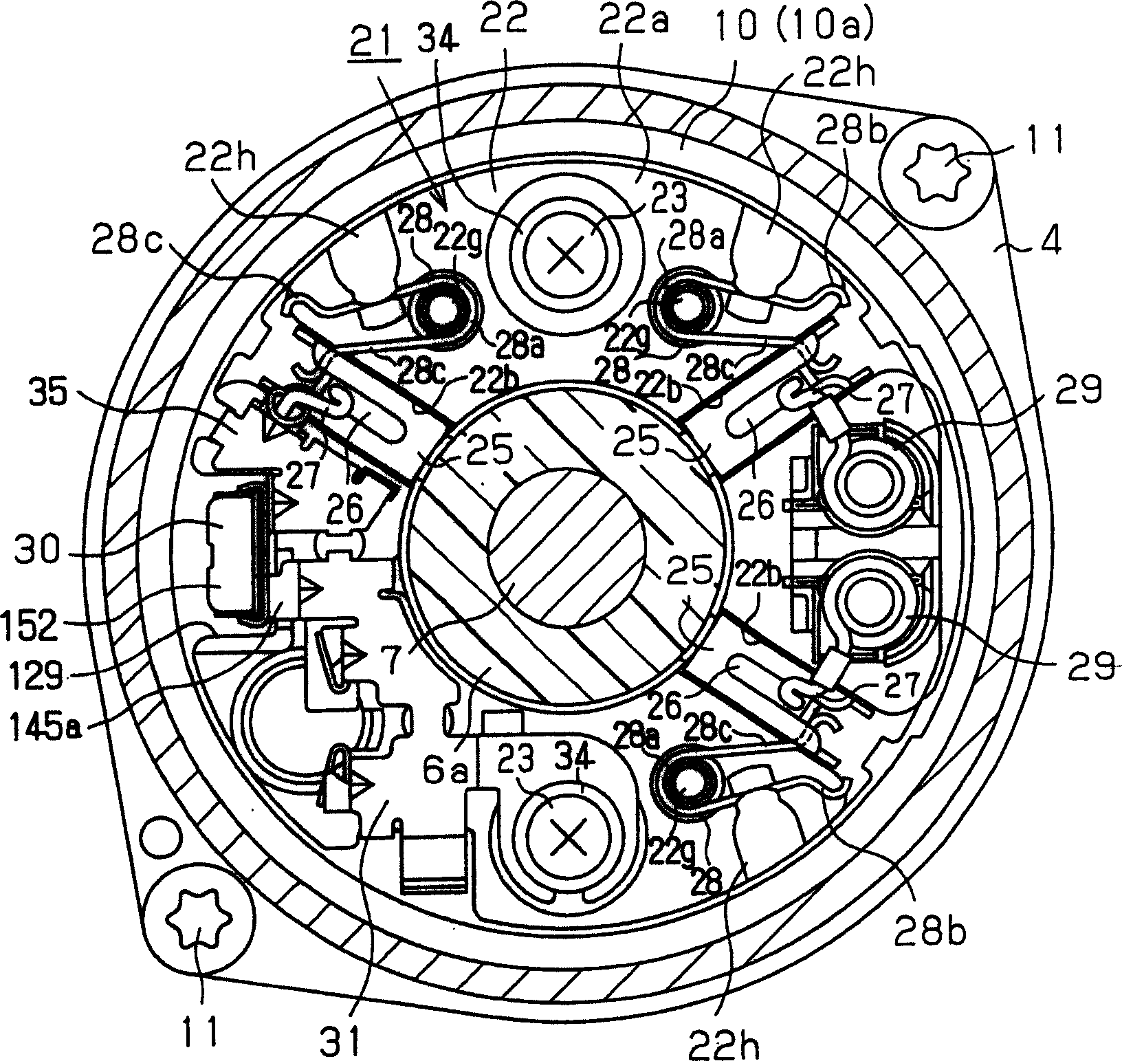
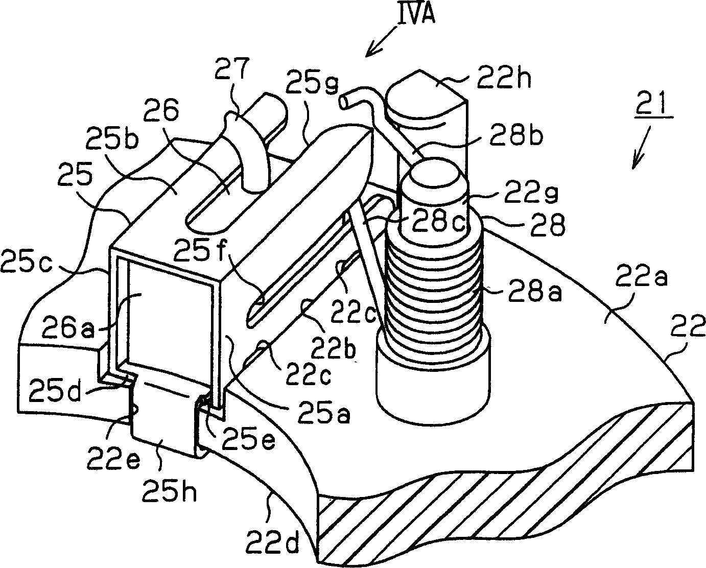
[0045] The yoke housing 4 of the motor unit 2 is made of a conductive metal material and formed into a cup shape. A plurality of magnets 5 are fixed to the inner peripheral surface of the yoke housing 4 . The armature 6 is rotatably accommodated in the yoke housing 4 at a corresponding position radially inward of the magnet 5 . A thrust bearing 8 and a radial bearing 9 are provided on the base of the yoke housing 4 , both of which rotatably support the base end of the rotatable shaft 7 of the armature 6 . The gear case 10 of the reduction unit 3 is assembled into the ...


PUM


Abstract

Brush holder device for dynamoelectric machine. Each brush holder is formed by bending a holder material made of a metal plate, so that the brush holder is shaped into a generally rectangular tubular body, which includes opposed first and second lateral walls, a top wall and a base wall. A base plate includes holder limiting grooves. Each brush holder is received in a corresponding one of the limiting grooves. The limiting groove limits an increase in a space between the first lateral wall and the second lateral wall of the corresponding brush holder. Furthermore, each brush is received in a corresponding one of the brush holders in a slidable manner in a sliding direction toward and away from a commutator of a motor.

Description

technical field [0001] The invention relates to a brush holder device for electromechanical machines. Background technique [0002] In a previously proposed brush holder for electromechanical machines (such as electric motors, generators), each brush is slidably accommodated in a corresponding brush holder fixed to a base plate in such a way that the brush is held relative to the armature by a spring. The commutator is urged to slidably engage the commutator. [0003] Japanese Unexamined Utility Model Publication No. 5-4750 discloses such a brush holder for a motor. In this brush holder arrangement, sheet metal material is bent so as to have a square horseshoe cross-section to form the brush holder. The lower opening of the brush holder is oriented towards the base plate (brush holder stay). In addition, the fixing claws of the brush holder are inserted through the corresponding fixing holes of the base plate, and are bent relative to the base plate to fix the brush holde...

Claims


Application Information

Patent Timeline
Patent Type & Authority Applications(China)
IPC IPC(8): H01R39/40H01R39/59H02K5/14H02K5/22H02K7/116
CPCH02K5/148H01R39/40H01R39/59H02K5/225H02K7/1166
Inventor 内田裕章
Owner DENSO CORP
Why Eureka
Try Eureka