

Cooling device and thin strap continuous casting apparatus and cooling method for casting thin strap
A technology of cooling device and cooling method, which is applied in the field of cooling device of thin strip continuous casting device and cooling device of cooling capacity, which can solve the problems of slow cooling and impossible adjustment of cooling speed, so as to slow down cooling speed and shorten cooling time , the effect of accelerating the cooling rate
- Summary
- Abstract
- Description
- Claims
- Application Information
AI Technical Summary
Problems solved by technology
Method used
Image

Examples
no. 1 Embodiment approach
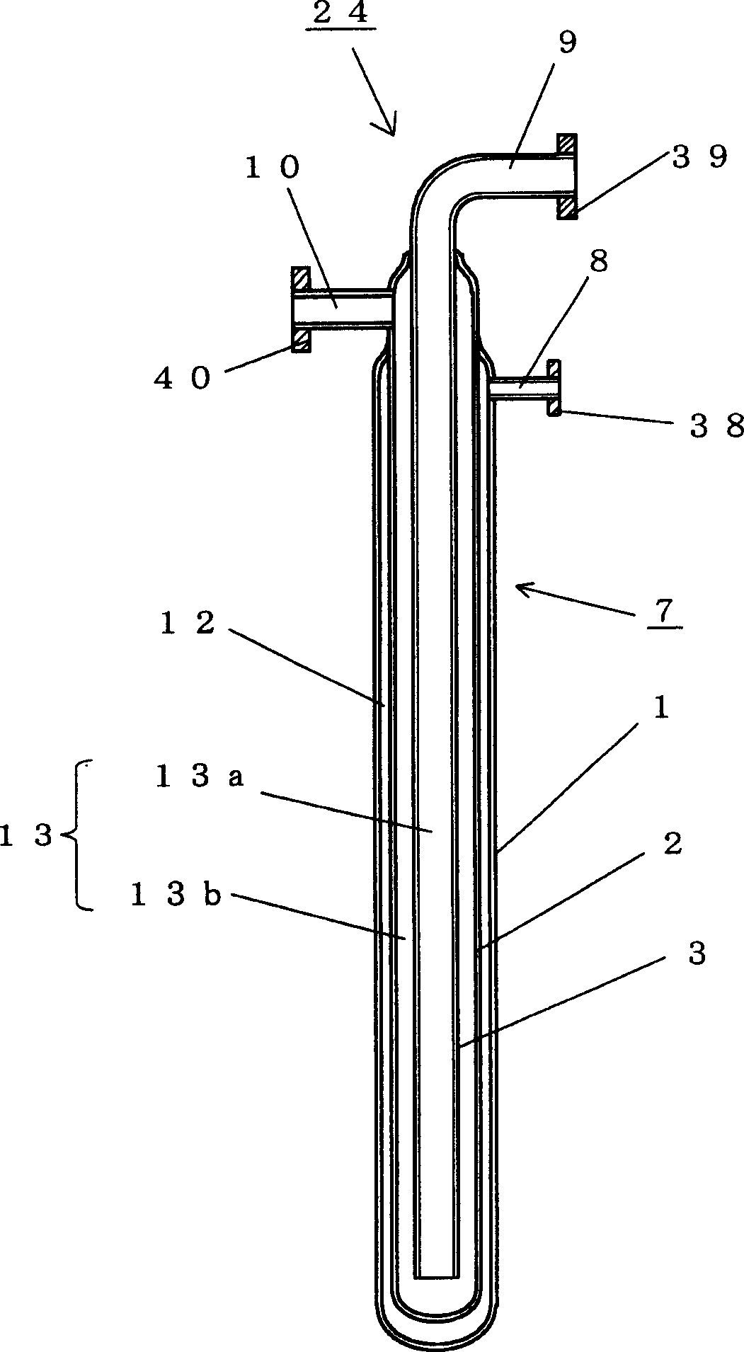
[0076] figure 1 A cross-sectional view of the cooling device according to the first embodiment of the present invention is shown in . This embodiment is the simplest example, and the cooling device is composed of a set of cooling pipe assemblies in a triple-pipe manner.
[0077] In the present invention, in order to realize above-mentioned task, as figure 1 As shown in , a cooling device 24 composed of a triple tube of a large-diameter outer tube 1 , a medium-diameter middle tube 2 and a small-diameter inner tube 3 is used. One end of the outer tube 1 of the cooling device is closed, and one end of the middle tube 2 is also closed inside the outer tube 1 . The other end of the outer tube 1 has a reduced diameter and is welded to the middle tube 2 .
[0078] One end of the inner pipe 3 is opened inside the middle pipe 2, the middle pipe 2 is the same as the outer pipe 1, the diameter of the other end is reduced, welded to the inner pipe 3, and a header 10 for the outlet of t...
no. 2 Embodiment approach
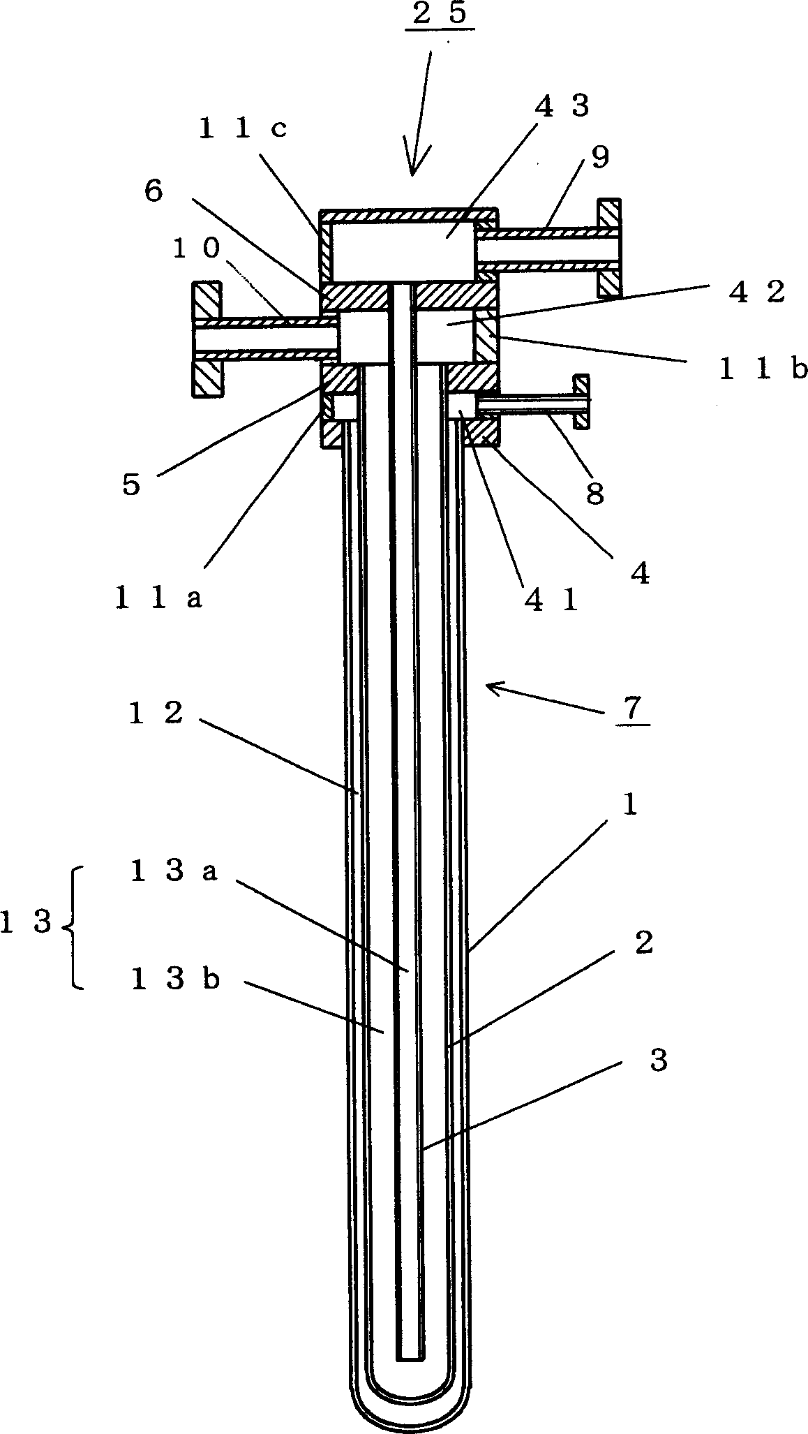
[0081] figure 2 A cross-sectional view of a cooling device 25 according to a second embodiment of the present invention is shown in . The difference between the cooling device 25 of this embodiment and the above-mentioned first embodiment is that the outer tube 1, the middle tube 2 and the inner tube 3 are respectively welded and fixed to the tube sheet 4 for the outer tube, the tube sheet 5 for the middle tube, and the tube sheet 6 for the inner tube. superior. Including the connection between the side plates 11a, 11b, 11c surrounding each tube plate 4, 5, 6 and the tube plate 4, 5, 6, all connections are welded connections, so that the headers 41, 42 and 43 are formed, which can Guaranteed air tightness. Other functions are the same as in Embodiment 1.
no. 3 Embodiment approach
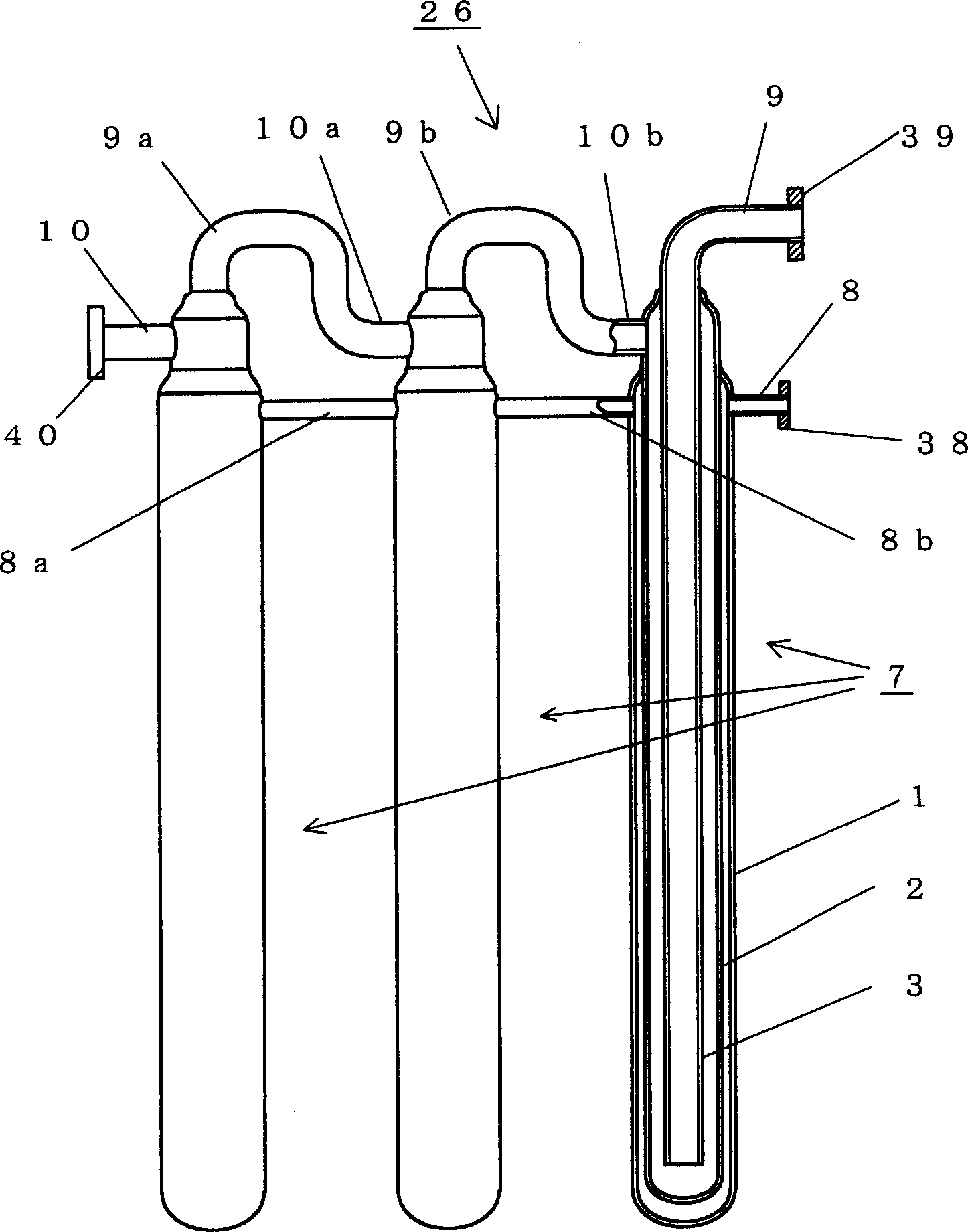
[0083] image 3 A front view showing a partial cross section of a cooling device according to a third embodiment of the present invention is shown in . This embodiment is an example in which the triple pipe type cooling pipe assemblies in the first embodiment are arranged in a row. The cooling medium outlet headers and inlet headers (9a-10a, 9b-10b) corresponding to the adjacent cooling pipes are connected, and the cooling medium flows through the paths of these cooling pipes in series. Simultaneously, the outer tubes 1 of adjacent cooling tube assemblies are connected to each other with headers 8a, 8b, and the annular gaps between the outer tubes and middle tubes of all cooling tube assemblies are simultaneously evacuated and gas for promoting cooling is introduced.
[0084] image 3 An example in which three cooling pipe assemblies are arranged in a row is shown, but the present invention is not limited to three cooling pipe assemblies, and the number can be increased, and...
PUM
| Property | Measurement | Unit |
|---|---|---|
| Outer diameter | aaaaa | aaaaa |
| The average thickness | aaaaa | aaaaa |
| The average thickness | aaaaa | aaaaa |
Abstract
Description
Claims
Application Information