Oil-jetting pump oil-quantity automatic measuring testing table

An automatic measurement and test bench technology, applied in the direction of engine testing, measuring devices, machine/structural component testing, etc., can solve problems such as low work efficiency and low measurement accuracy

Inactive Publication Date: 2005-02-16
HENAN UNIV OF SCI & TECH
View PDF0 Cites 11 Cited by
  • Summary
  • Abstract
  • Description
  • Claims
  • Application Information

AI Technical Summary

Problems solved by technology

At present, the fuel injection pump test bench usually adopts the method of artificial visual test tube in the measurement method of fuel quantity. When using this method to measure, it needs to collect hundreds of times of fuel injection with glass test tubes, and the work eff

Method used


Image

  • Oil-jetting pump oil-quantity automatic measuring testing table
  • Oil-jetting pump oil-quantity automatic measuring testing table

Examples


Embodiment Construction

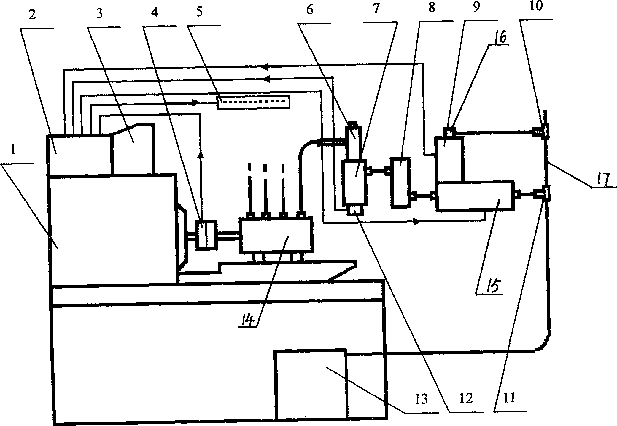
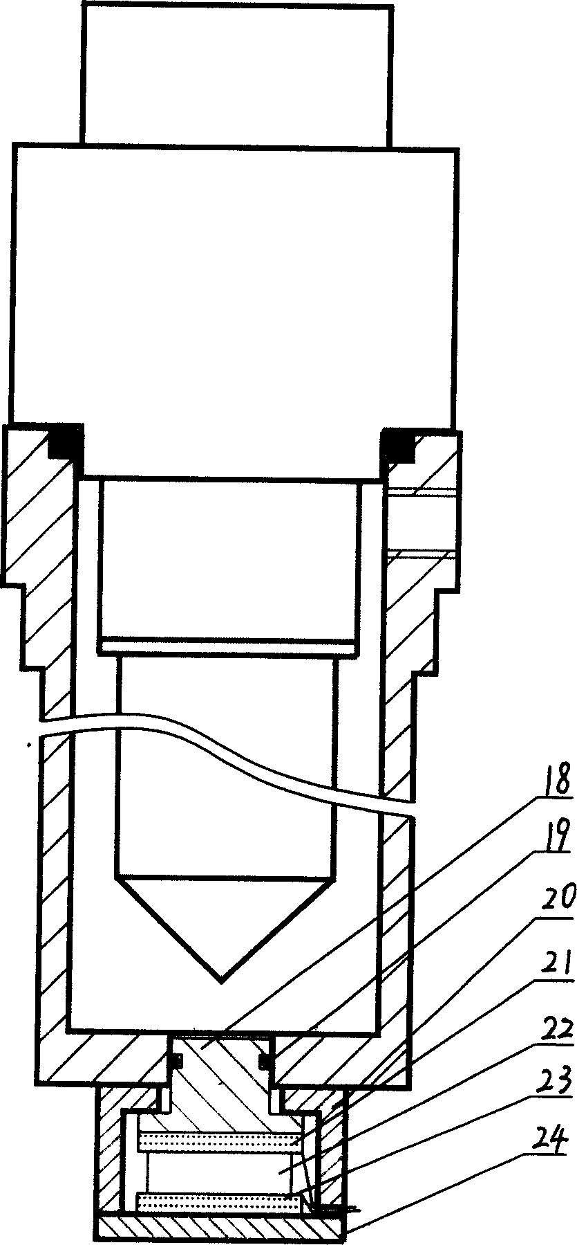
[0012] Such as figure 1 , figure 2 As shown, the test bench of the present invention includes a fuel injector 6, an oil collector 7, a defoaming regulator 8, an oil production and discharge solenoid valve 15 and a flow sensor 9, and between the inlet of the fuel injector 6 and the outlet of the oil pump 14 The oil collector 7 is installed on the outlet of the injector 6. The outlet of the oil collector 7 is connected to the defoaming regulator 8 through a conduit. The inlet of valve 15 links to each other, and flow sensor 9 is installed on the oil production and discharge solenoid valve 15, and the oil outlet 16 of flow sensor 9 and the oil outlet of production and discharge solenoid valve 15 link to each other with oil tank 13 by oil return pipe 17 respectively. The flow sensor in this embodiment is a volumetric sensor, and the volumetric sensor is a circular tube sensor. An upper and a lower pair of photoelectric sensors are respectively installed on the opposite sides of ...


PUM


Abstract

This invention relates to a test stand for automatically measuring volume of an oil spray pump including a sprayer, a collector, a deforming stabilizer, a collect/discharge electromagnetic valve and a flow sensor, among which, the oil collector is mounted on the outlet of the oil sprayer connected with the deforming regulator via conduit, outlet of which is linked to the inlet of the collect/discharge valve, the flow sensor is mounted on the valve, the top overflow lip of the sensor and outlet of the valve are connected with the oil tank via return tubes which applies the sensor in the collector to determine it the pump is at the spraying state, either solves the problem of costing too long time to test small volume by single volume flow sensor or complicated structure of a multi-volume flow sensor.

Description

technical field [0001] The invention relates to a fuel injection pump fuel quantity automatic measurement test bench which can automatically measure the fuel injection quantity of each cylinder and the dynamic fuel injection phase angle of each cylinder Background technique [0002] Fuel injection pump test bench is the equipment used for adjusting and checking the fuel injection pump of diesel engine. At present, the fuel injection pump test bench usually adopts the method of artificial visual test tube in the measurement method of fuel quantity. When using this method to measure, it needs to collect hundreds of times of fuel injection with glass test tubes, and the work efficiency is low; and the reading is done with the naked eye. Observe and read the scale of the oil level on the test tube, the measurement accuracy is low. In addition, the existing fuel injection pump test bench can only measure the static fuel supply phase angle of each cylinder. Contents of the inve...

Claims


Application Information

Patent Timeline
IPC IPC(8): F02M65/00
Inventor 赵致和朱邦太邓本都宗永平李勋刘建新李民刘建亭杜慧勇
Owner HENAN UNIV OF SCI & TECH
Why Eureka
Try Eureka