Ultrasonic micro driving friction test system

A test system and friction testing machine technology, applied in the direction of generator/motor, piezoelectric effect/electrostrictive or magnetostrictive motor, measuring device, etc., can solve the problem of not establishing an accurate friction drive model

Inactive Publication Date: 2005-02-16
HARBIN INST OF TECH
View PDF0 Cites 14 Cited by
  • Summary
  • Abstract
  • Description
  • Claims
  • Application Information

AI Technical Summary

Problems solved by technology

Due to the complexity of the friction phenomenon itself, and the fact that the stator and rotor are in high-frequency (tens of kilohertz) and micro-amplitude (several micrometers) vibration contact conditions, the friction driving mechanism is still inconclusive

Method used


Image

  • Ultrasonic micro driving friction test system
  • Ultrasonic micro driving friction test system
  • Ultrasonic micro driving friction test system

Examples


specific Embodiment approach 1

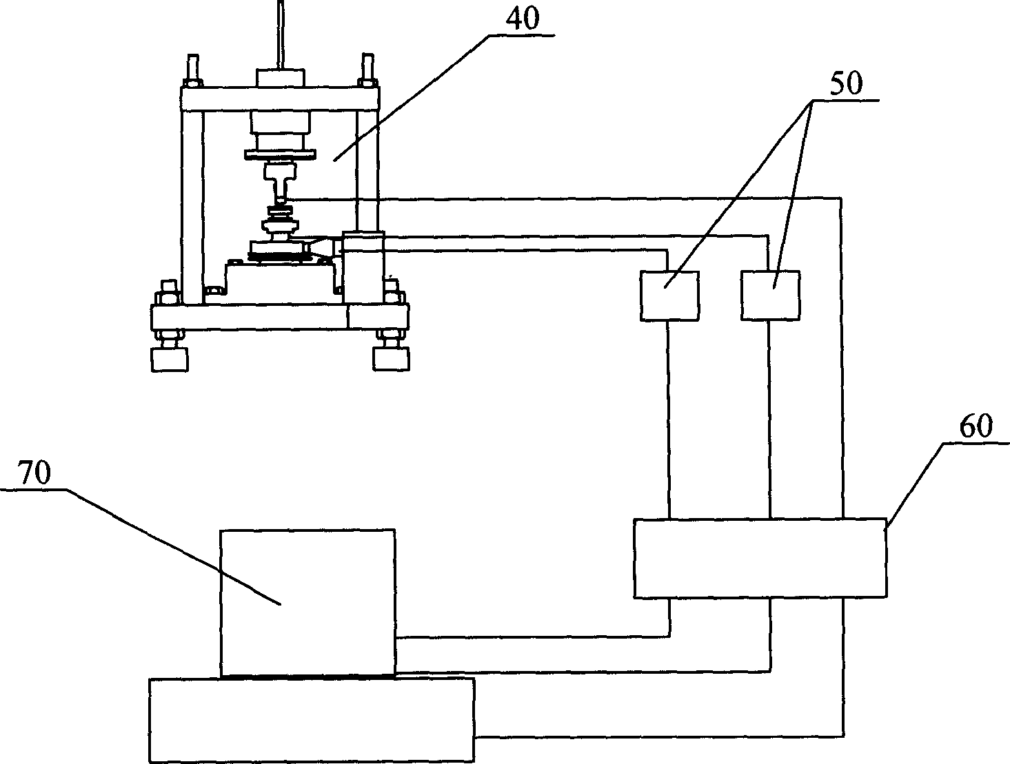
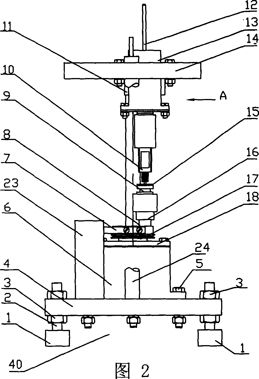
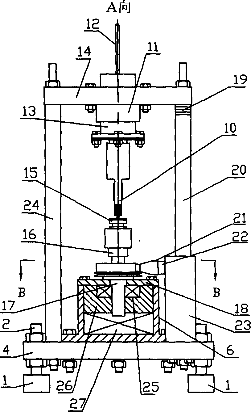
[0005] Specific embodiment one: (see Figure 1-Figure 6 ) This embodiment consists of an ultrasonic micro-drive friction tester 40, a charge amplifier 50, a terminal board 60, and a microcomputer 70. The ultrasonic micro-drive friction tester 40 is connected to the charge amplifier 50 and the terminal board 60 by wires, respectively. The amplifier 50 is connected to the terminal board 60 by wires, and the terminal board 60 is connected to the microcomputer 70 by wires. The ultrasonic micro-drive friction tester 40 consists of a support 1, a foot column 2, a leveling nut 3, a lower connecting plate 4, a connecting bolt 5, a sleeve 6, a driving force output beam 7, an instantaneous dynamic positive pressure sensor 8, and a sample tray 9. , Ultrasonic vibrating body 10, clamping sleeve 11, weight fixing rod 12, loading sleeve 13, upper connecting plate 14, friction material layer 15, bearing sleeve 16, T-shaped transmission output shaft 17, bearing end cover 18, pad Consists of sheet ...

specific Embodiment approach 2

[0006] Specific implementation manner two: (see Figure 7 ) The difference between the ultrasonic vibrator 10 in this embodiment and the first embodiment is that the ultrasonic vibrator 10 is composed of a friction drive head 31, a front matching block 32, a longitudinal excitation piezoelectric sheet 33, a bending excitation piezoelectric sheet 34, A flange 35, a connecting bolt 36, and a rear matching block 37 are formed. Between the front matching block 32 and the rear matching block 37, two longitudinal excitation piezoelectric sheets 33 are sequentially fixed by the connecting bolt 36. The flange 35, two The longitudinal excitation piezoelectric sheet 33 has a bending excitation piezoelectric sheet 34 fixed on both sides of the friction drive head 31. The other composition and connection relationship are the same as in the first embodiment. This is a rod-plate combined ultrasonic vibrator. For the rod-plate combined ultrasonic vibrator, the longitudinal ultrasonic vibration i...

specific Embodiment approach 3

[0007]Specific embodiment three: (see FIG. 8) The difference between the ultrasonic vibrating body 10 in this embodiment and the first embodiment is that the ultrasonic vibrating body 10 is composed of a double body structure, and each single body is composed of a friction drive head 31 and a front matching It consists of a block 32, eight longitudinal excitation piezoelectric sheets 33, a flange 35, a connecting bolt 36, and a rear matching block 37. Four longitudinal sheets are fixed between the flange 35 and the front matching block 32 and the rear matching block 37. Exciting piezoelectric sheet 33, two flange plates 35 are fixedly butted, and two friction drive heads 31 are connected and fixed together at a 90° angle, and their diagonal outer surfaces are round. The other composition and connection relationship are the same as in the first embodiment. This is a dual longitudinal compound ultrasonic vibrator. For the double-longitudinal composite ultrasonic vibrator (see Figure...


PUM


Abstract

This ultrasonic mini-driven friction tester comprises the electric charge amplifier, which is connected, with the electric charge ampifier and terminal block (60) by wire, and the terminal block is connected with mini-computer by the wire. This invention can equivalently imitate driven procession of rotator on which certain opposite point with the ultrasonic electric motor's stator be stirred friction materials, and can survey between the different friction materials instantaneous microcosmic condition mini, normal pressure and friction force in real time, then can gain the different friction materials on the instantaneous microcosmic condition the friction coefficient. It can study the ultrasonic electric motor intrinsic features on the different friction materials, such as the driven voltage and temperature exchange how the influence ultrasonic electric motor's instantaneous microcosmic condition fricative driven function.

Description

Technical field: [0001] The invention relates to an ultrasonic friction test system. Background technique: [0002] Ultrasonic motors based on the inverse piezoelectric effect of piezoelectric crystals and powered by contact friction drive have many characteristics that traditional electromagnetic motors do not have. They have been used in aerospace, robots, automobiles, precision positioning, medical machinery, micro machinery, etc. The field is successfully applied. Among them, the stator surface particles of the traveling wave ultrasonic motor make an elliptical motion, and the continuous surface particles form a traveling wave, and the rotor is driven by the surface traveling wave friction. The contact between the stator and rotor of the traveling wave ultrasonic motor is relatively stable and continuous, and the output characteristics of the motor are relatively stable. Compared with other ultrasonic motors, it is widely used and is more practical for micro and precision ins...

Claims


Application Information

Patent Timeline
IPC IPC(8): G01N19/02H02N2/12H02N2/14
Inventor 曲建俊高绘罗云霞
Owner HARBIN INST OF TECH
Why Eureka
Try Eureka