Magnetic flow liquid variable controllnig valve with two liquid flow resistance channels

A magneto-rheological fluid and control valve technology, applied in fluid pressure actuation devices, fluid pressure actuation system components, servo motors, etc. Problems such as flow resistance channels, etc., to achieve the effect of being suitable for mass production, increasing the shear area, and uniform radial size

Inactive Publication Date: 2005-02-23
CHONGQING UNIV
View PDF0 Cites 15 Cited by
  • Summary
  • Abstract
  • Description
  • Claims
  • Application Information

AI Technical Summary

Problems solved by technology

At present, the concept of magnetorheological fluid control valve mostly adopts a single flow resistance channel, the area of ​​the flow resistance channel is small, and the resulting flow resistance is limited.
In order to realize the effective control of the magnetorheological fluid, only increase the structural size and (or) the working current; at the same time, there are problems such as complicated positioning of the valve core

Method used


Image

  • Magnetic flow liquid variable controllnig valve with two liquid flow resistance channels
  • Magnetic flow liquid variable controllnig valve with two liquid flow resistance channels
  • Magnetic flow liquid variable controllnig valve with two liquid flow resistance channels

Examples


Embodiment Construction

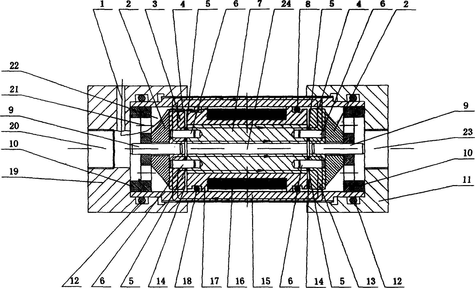
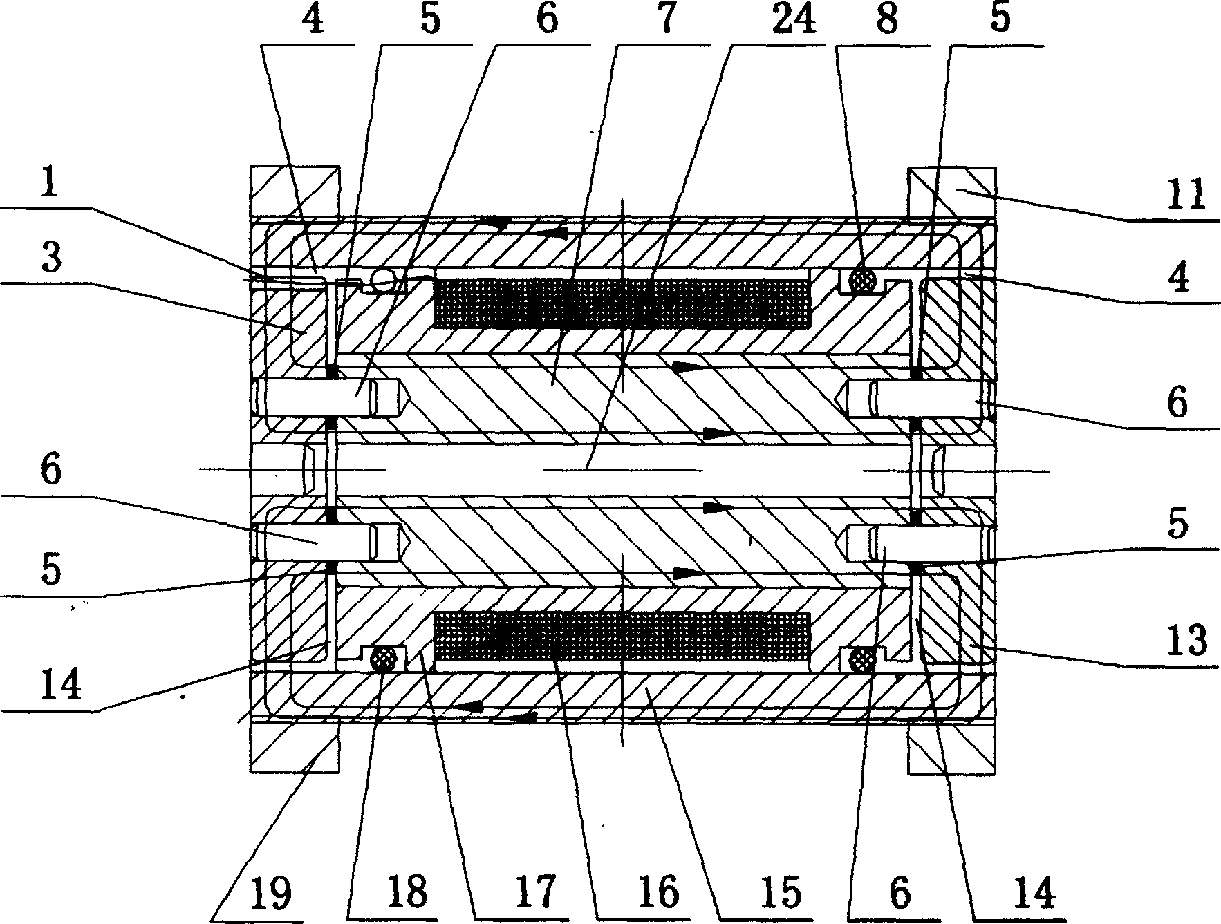
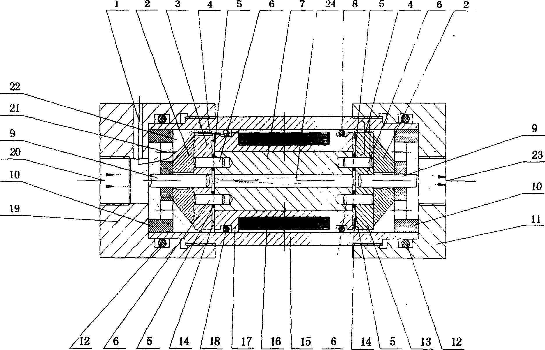
[0029] Below in conjunction with accompanying drawing, structure of the present invention will be further described:

[0030] In the drawings: 1 is the lead wire, 2 is the guide block, 3 is the magnetic disc at the end of the lead wire, 4 is the annular liquid flow resistance channel, 5 is the non-magnetic gasket, 6 is the connecting pin, 7 is the valve core, 8 is a sealing ring, 9 is a positioning pin, 10 is a positioning block, 11 is a valve end cover, 12 is a sealing ring between the end cover and the cylinder, 13 is a magnetic disc, and 14 is a disc-shaped liquid flow resistance channel , 15 is the cylinder, 16 is the excitation coil, 17 is the non-magnetic wire rack, 18 is the sealing ring on the lead wire side of the wire rack, 19 is the valve end cover on the lead wire side, 20 is the liquid inlet hole, 21 is the diversion hole , 22 magnetorheological fluid, 23 is the liquid outlet, 24 is the center hole of the valve core

[0031] Refer to attached figure 1 , is a str...


PUM


Abstract

A valve is used for continuous regulating and/or cutting-off magnetic rheological fluid. It has an annular drag channel and a circular drag channel. The external magnetic path is formed by a cylinder, a magnet-conducting disc and the said both channels. The core of the said valve is used as the internal magnetic path. The gap of the annular drag channel depends on precise transition fit of the cylinder and the positioning block, which is connected with the magnet-conducting disc by a pin. The thickness of the circular drag channel depends on cushions on a connecting pin of the said core. Neither pin nor cushions are of magnet-conducting material. A strong resistance of flow can be generated by a little electric current. The valve has a larger range of control, little energy consumption, small size and is light and simple, easy to mass production.

Description

technical field [0001] The patent of the invention belongs to the field of hydraulic control valves, and specifically relates to a magneto-rheological fluid control valve with two kinds of fluid flow resistance channels. technical background [0002] The hydraulic control valve is one of the core components of the hydraulic system. In the hydraulic system, the hydraulic control valve is used to control the pressure, flow and flow direction of the liquid flow in the hydraulic system, thereby controlling the start and stop of the hydraulic actuators, changing the speed, direction, force and action sequence of the movement, etc., to meet various requirements. Requirements for movement, speed, force and torque of similar hydraulic equipment. Therefore, the performance of the hydraulic control valve directly affects the static characteristics, dynamic characteristics and working reliability of the hydraulic system. [0003] Due to the existence of moving mechanical parts, tradi...

Claims


Application Information

Patent Timeline
Patent Type & Authority Applications(China)
IPC IPC(8): F15B11/02F15B11/04F15B21/02
Inventor 王代华艾红霞
Owner CHONGQING UNIV
Why Eureka
Try Eureka