
Method and device for realiznig multiple light path automatic balance regulation in laser phototypesetting
An automatic balancing and multi-optical path technology, which is applied in the field of multi-optical path scanning optical equipment, can solve problems such as time drift, temperature drift, light spot imbalance, and transfer coefficient difference that cannot adapt to LD, so as to solve the problem of power imbalance and improve Scanning imaging accuracy, the effect of overcoming Moiré fringe phenomenon
- Summary
- Abstract
- Description
- Claims
- Application Information
AI Technical Summary
Problems solved by technology
Method used
Image


Examples
Embodiment Construction
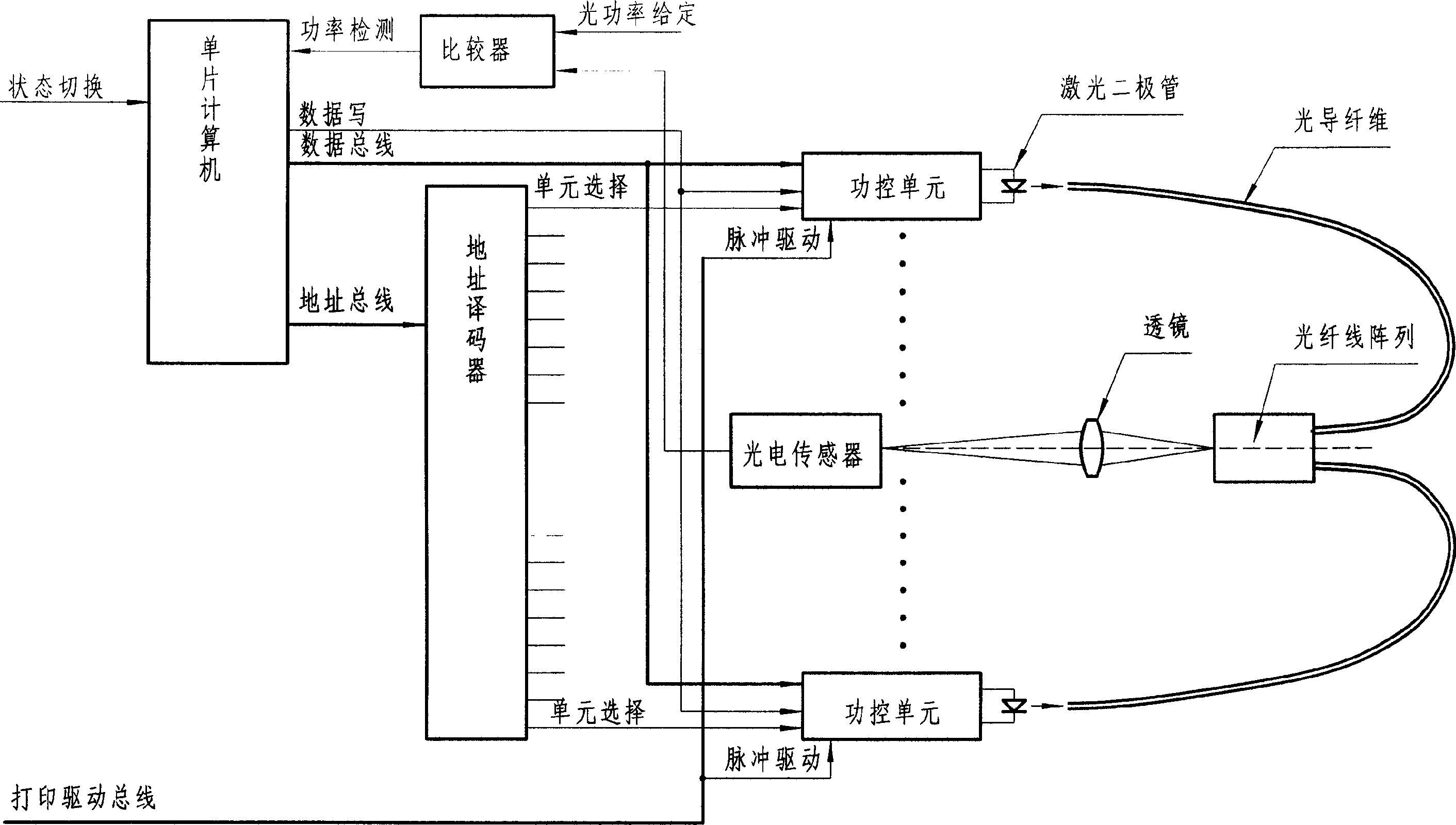
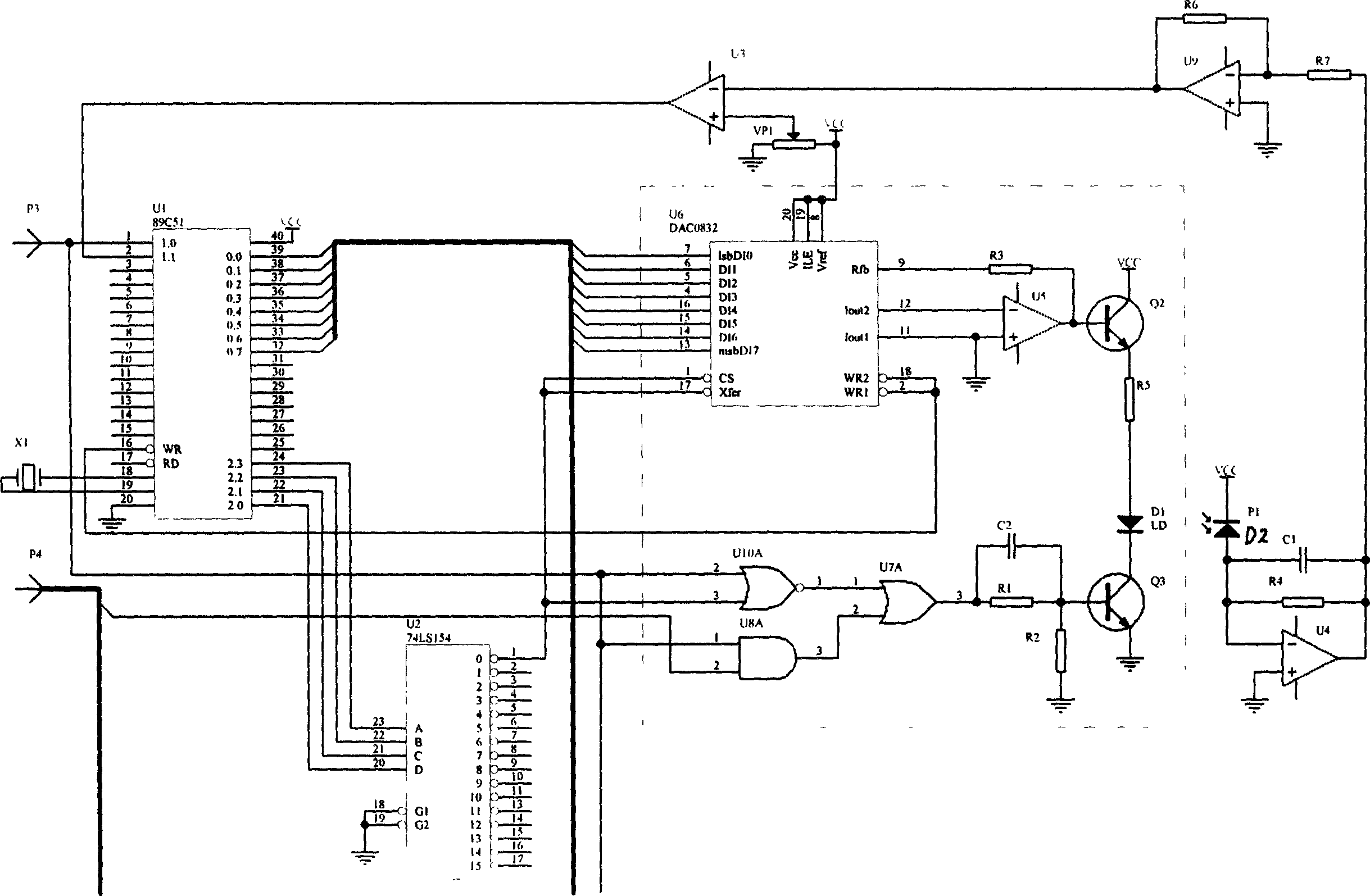
[0021] The present invention is mainly used in the multi-channel light scanning imaging system in the laser phototypesetting, aims to propose a fully automatic, real-time adjustment scheme controlled by a computer, in order to solve the problems in the conventional method (see figure 1 ). The core idea is to switch the regulating circuit between two states: either a calibration state or a scanning state. In the calibration state, the photoelectric sensor is used to detect the optical power behind the mirror, and the outgoing beam will be aimed at the photoelectric sensor. The single-chip computer selects the power control unit of each light in turn through the address decoder, and lights up the light. At the same time, the photoelectric sensor collects the light intensity of the road, compares it with a given value, and sends a signal that is greater than or less than to the computer. Based on this, the computer resets the unit through the data bus - either decreases or incr...
PUM
 Abstract
Description
Claims
Application Information