Precipitation pneumatically supported serial composite solid-liquid separator
A technology of solid-liquid separation and series combination, which is applied in the direction of precipitation separation, solid separation, separation methods, etc., can solve the problem of large footprint, single solid-liquid separation device cannot adapt to the change of source water quality, and affect the effective adhesion of air bubbles and flocs. Additional questions
- Summary
- Abstract
- Description
- Claims
- Application Information
AI Technical Summary
Problems solved by technology
Method used
Image
Examples
specific Embodiment approach 1
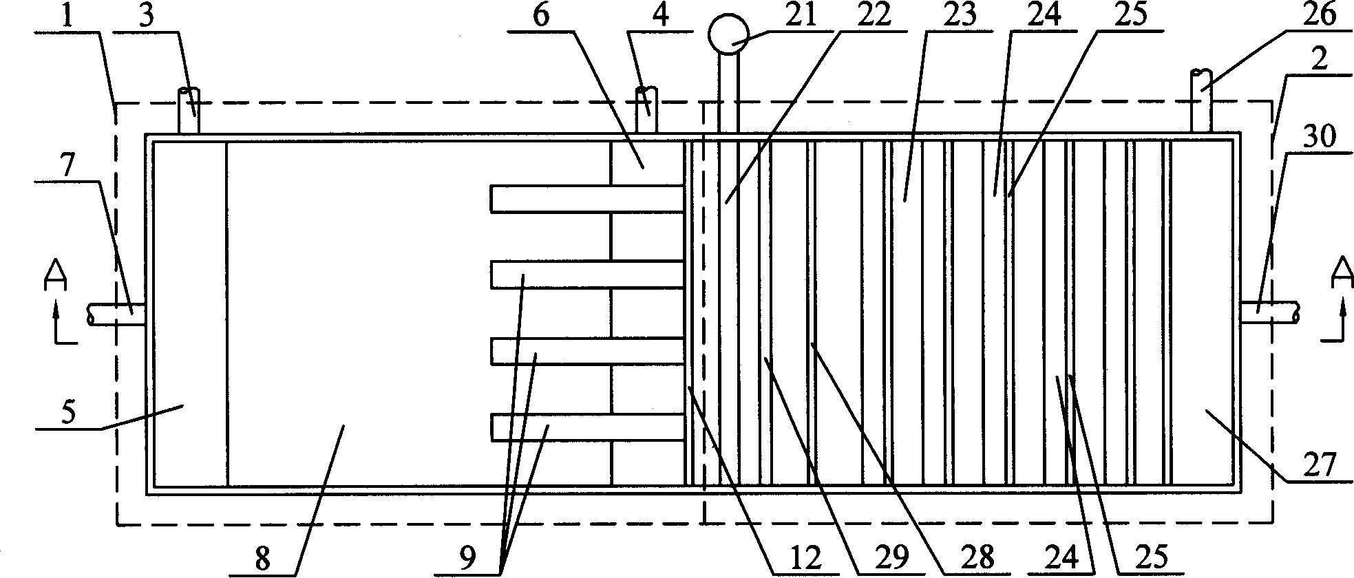
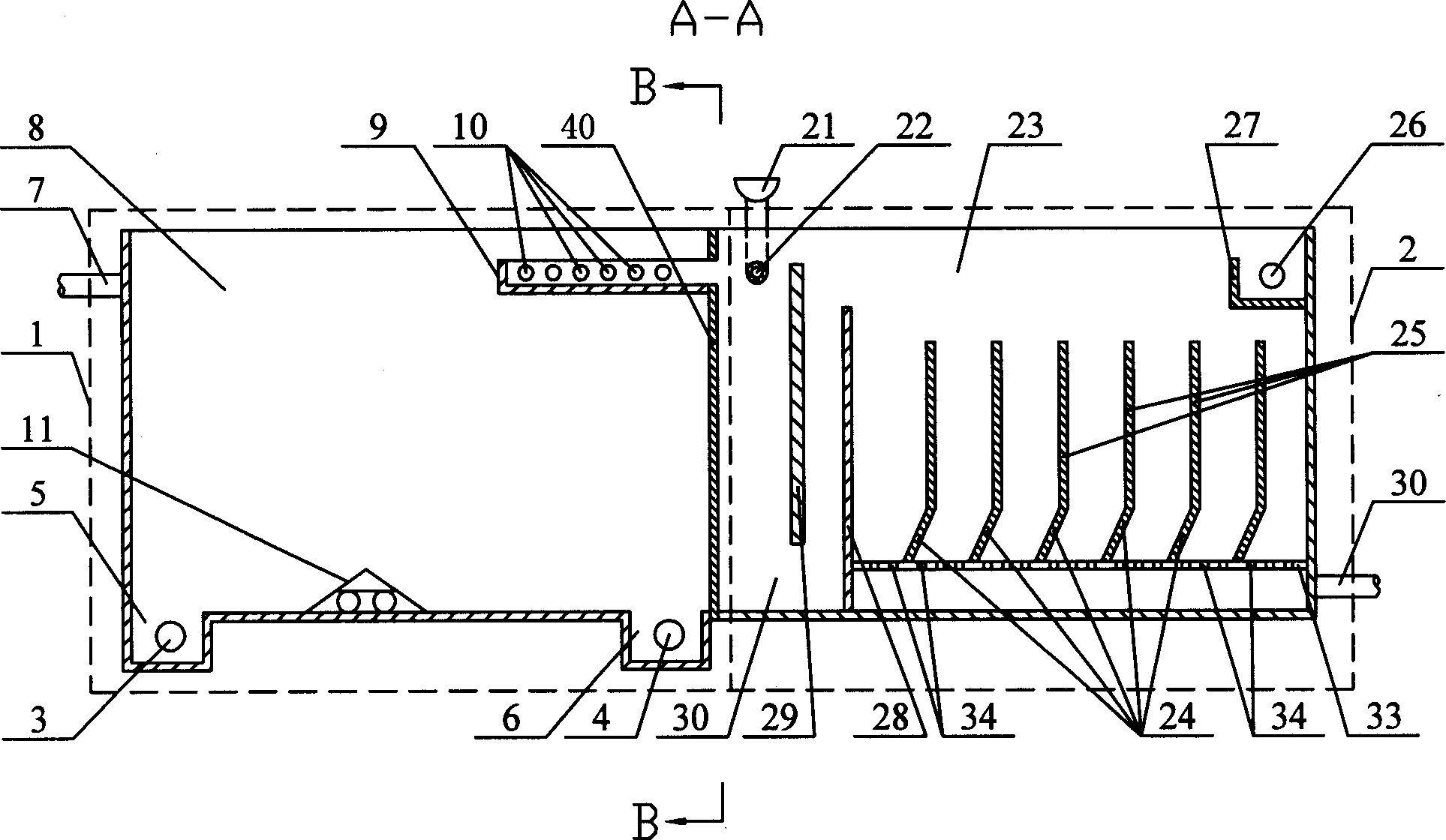
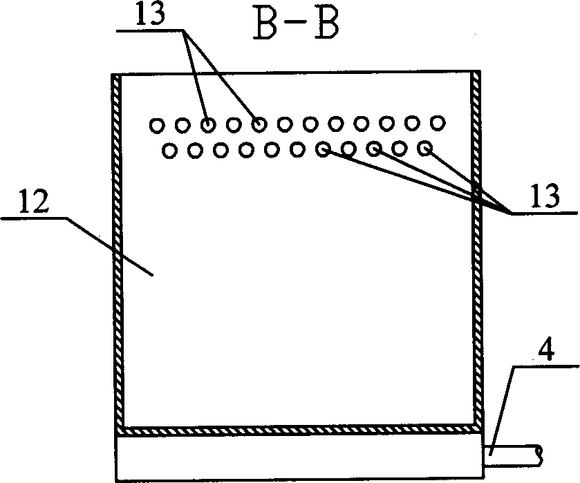
[0005] Specific implementation mode one: (see Figure 1 ~ Figure 3 ) This embodiment consists of a sedimentation solid-liquid separation device 1 and an air flotation solid-liquid separation device 2, and the precipitation solid-liquid separation device 1 and the air flotation solid-liquid separation device 2 are connected in series. The precipitation solid-liquid separation device 1 is composed of a sedimentation tank 8, a water inlet channel 7, a perforated flower wall 12, a No. 1 sludge tank 5, a No. 1 slag outlet 3, a No. 2 sludge tank 6, and a No. 2 slag outlet 4; The water channel 7 is set on the water inlet side of the sedimentation tank 8, the perforated flower wall 12 is set on the water outlet side of the sedimentation tank 8, the perforated flower wall 12 has a water outlet hole 13, and the No. 1 sludge tank 5 is set on the water inlet of the sedimentation tank 8 At the bottom of one side, No. 1 slag outlet 3 is arranged on the outer wall of sedimentation tank 8 at ...
specific Embodiment approach 2
[0006] Specific implementation mode two: (see figure 1 , figure 2 ) The difference between this embodiment and the specific embodiment one is that the first mixing plate 29, the second mixing plate 28, the perforated pipe 22 and the high-level medicine box or the dosing pump 21 are added in the air flotation tank 23, and the first mixing plate 29 is fixed on the water inlet side in the air flotation pool 23, the lower end of the first mixing plate 29 and the bottom surface of the air flotation pool 23 leave a water space 30, and the second mixing plate 28 is fixed in the air flotation pool 23 close to the first mixing plate 29 on the water outlet side, the lower end of the second mixing plate 28 is sealed and connected with the bottom surface of the air flotation pool 23, the height of the upper end of the second mixing plate 28 is lower than the height of the upper end of the first mixing plate 29, and the first mixing plate 29 and the perforated flower wall The upper part ...
specific Embodiment approach 3
[0007] Specific implementation mode three: (see figure 2 ) The difference between this embodiment and the specific embodiment one is that the perforated flower wall 12 and the water outlet hole 13 are replaced by the water collection tank 9 and the retaining wall 40, the water collection tank 9 is provided with a through hole 10, and the water collection tank 9 and the retaining wall 40 are vertically arranged , One end of the sump 9 is fixed on the retaining wall 40 and communicates with the air flotation pool 23 . Other compositions and connections are the same as in the first embodiment. The function of this embodiment is to make the water outlet of the sedimentation tank 8 uniform, which is beneficial to improve the treatment effect of the air flotation tank 23 .
PUM
 Abstract
Description
Claims
Application Information
 - R&D
- Intellectual Property
- Life Sciences
- Materials
- Tech Scout
- Unparalleled Data Quality
- Higher Quality Content
- 60% Fewer Hallucinations
Browse by: Latest US Patents, China's latest patents, Technical Efficacy Thesaurus, Application Domain, Technology Topic, Popular Technical Reports.
© 2025 PatSnap. All rights reserved.Legal|Privacy policy|Modern Slavery Act Transparency Statement|Sitemap|About US| Contact US: help@patsnap.com


