Optically driven therapeutic radiation source

A technology of radiation source and optical radiation, which is applied in the field of therapeutic radiation source, and can solve problems such as reduced efficiency of x-rays and damage to x-ray stability

Inactive Publication Date: 2005-03-16
KODENSHI
View PDF5 Cites 13 Cited by
  • Summary
  • Abstract
  • Description
  • Claims
  • Application Information

AI Technical Summary

Problems solved by technology

If electrons are deflected to the wall by the insulating charging effect, the effici

Method used


Image

  • Optically driven therapeutic radiation source
  • Optically driven therapeutic radiation source
  • Optically driven therapeutic radiation source

Examples


Embodiment Construction

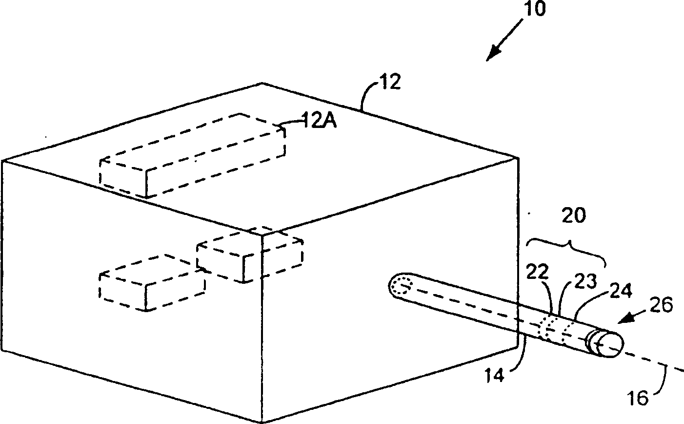
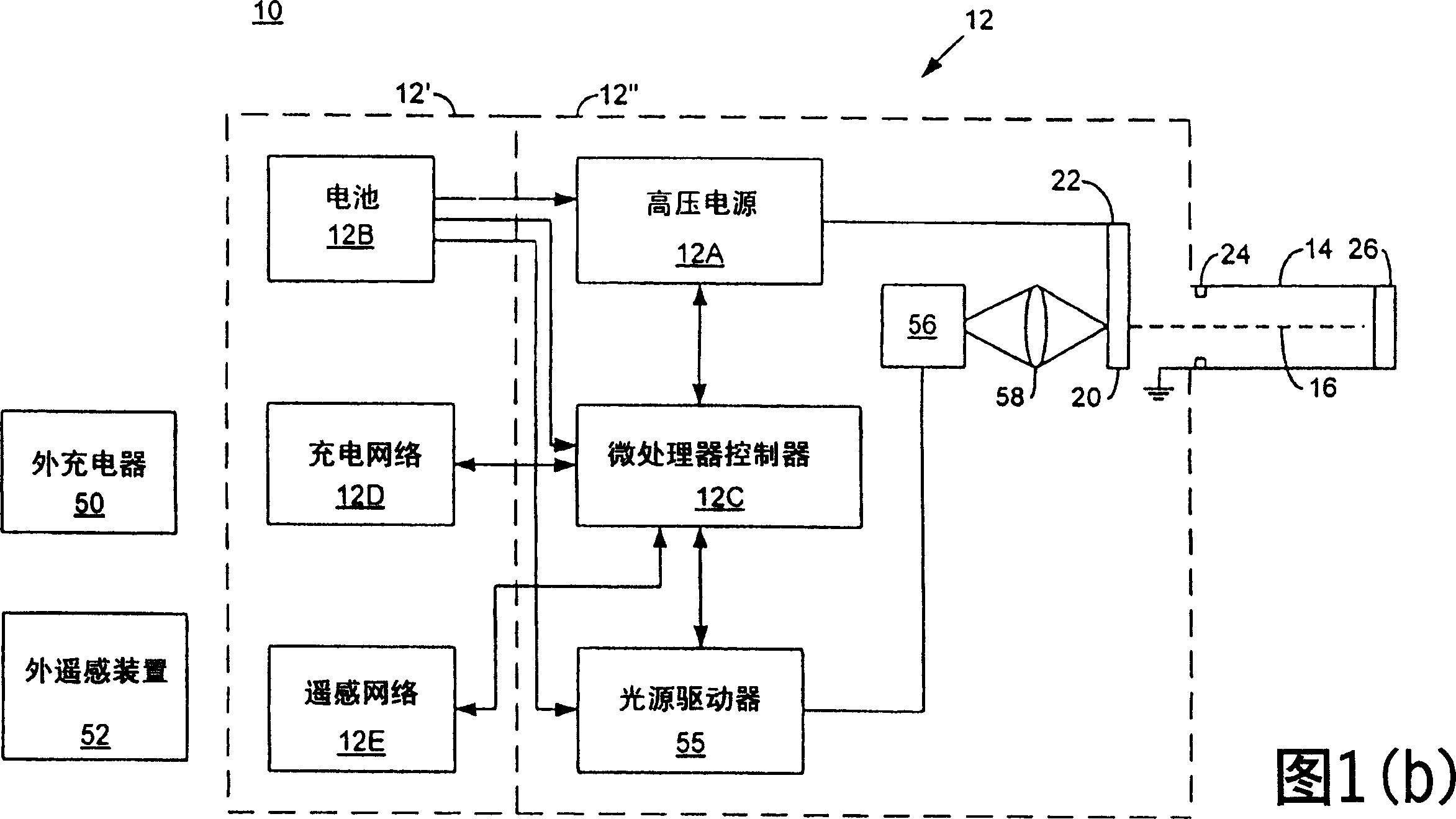
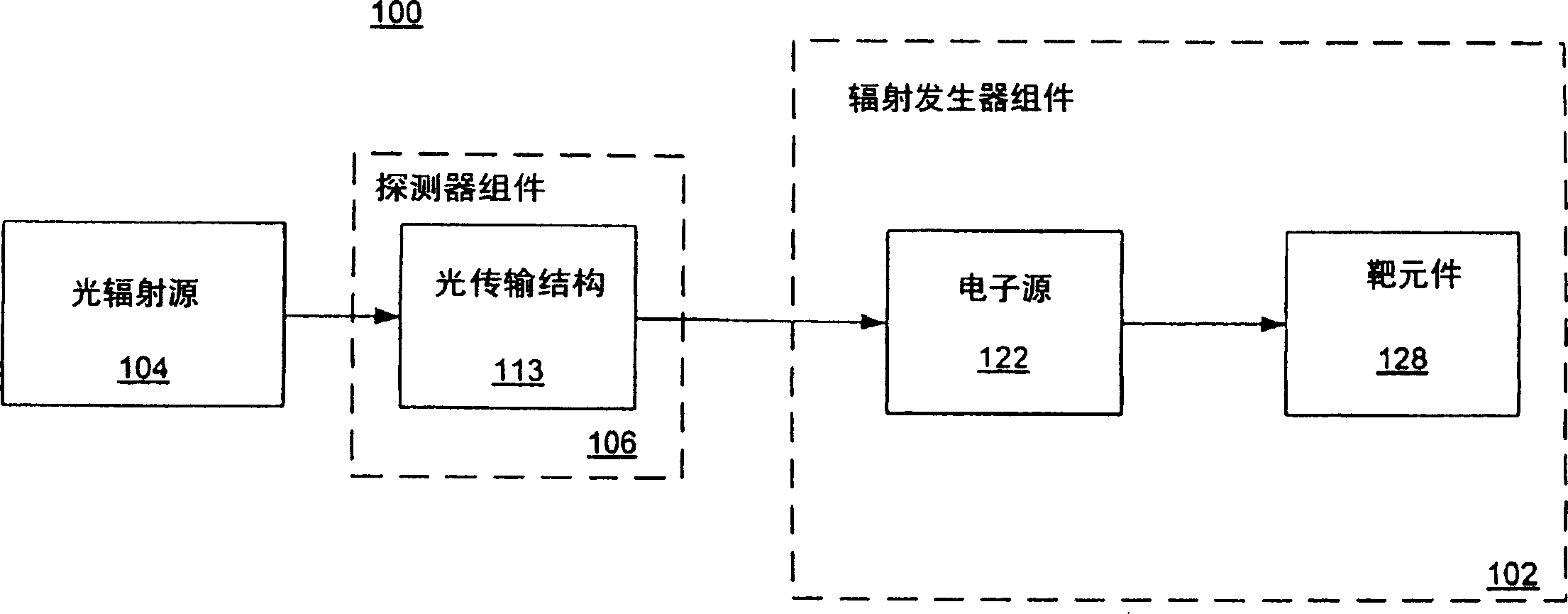
[0039] The present invention relates to a small, low-power source of therapeutic radiation for use in the diagnosis, treatment, and relief therapy of patients. In the present invention, a laser is used to heat the thermionic cathode to electron emission temperature. The power requirements of the therapeutic radiation source are significantly reduced compared to systems with resistively heated thermionic cathodes. Therapeutic radiation produced by the devices of the present invention may include, but is not limited to, x-rays. In medical applications, the device may be fully or partially implanted in, or surface mounted on, a desired region of the host in order to irradiate a preselected region with therapeutic radiation. The devices of the present invention can be operated at lower voltages, eg, in the range of about 10 KeV to 90 KeV, with electron currents, eg, in the range from about 1 nA to about 1 μA.

[0040] Figure 1(a) shows a therapeutic radiation source 10 which gen...


PUM

PropertyMeasurementUnit
Diameteraaaaaaaaaa
Lengthaaaaaaaaaa

Abstract

A miniaturized, optically driven therapeutic radiation source (100) includes a laser-heated thermionic cathode (122). A fiber optic cable (113) directs a light beam from an optical source (104) to impinge upon a surface of the thermionic cathode (122), heating the surface to a temperature sufficient to cause thermionic emission of electrons. The target element (128) emits therapeutic radiation, such as x-rays, in response to incident accelerated electrons from the electron beam. In one embodiment, the electron source (122) and the target element (128) are disposed within a capsule (130) which defines a substantially evacuated region. The inner surface of the capsule is coated with a semiconductor coating, so that a uniform voltage gradient is maintained within the evacuated capsule. In another embodiment, the thermionic cathode (300) is formed of a spiral-shaped conductive element (310) having a plurality of spaced-apart turns. Interstitial spacing between adjacent turns essentially eliminates heat transfer across the spacin.

Description

technical field [0001] The present invention relates to therapeutic radiation sources, and more particularly to radiation sources utilizing optically driven thermionic cathodes, which provide reduced power, increased efficiency and miniaturization. Background technique [0002] In the medical field, therapeutic radiation, such as x-ray radiation and gamma radiation, is used to diagnose, treat and administer relief therapy to patients. Traditional medical radiation sources for such treatments include large fixed-position machines, and small, portable radiation-generating detectors. Prior art treatment systems utilize computers to generate complex treatment plans. [0003] Conventional radiation systems used in medical treatment utilize high-energy distant radiation sources and direct beams of radiation toward a target area, such as a tumor within a patient's body. This type of treatment is called teletherapy because the radiation source is located a predetermined distance f...

Claims


Application Information

Patent Timeline
IPC IPC(8): G21K5/02A61N5/10G21K1/06H01J35/06H01J35/08H01J35/32
CPCH01J35/32H01J35/06A61N5/1001H01J2235/164G21K1/06A61N2005/1022H01J35/064
Inventor 马克·丁斯莫尔
Owner KODENSHI
Why Eureka
Try Eureka