Megneto-optical optical element
An optical component, magneto-optical technology, applied in optics, nonlinear optics, instruments, etc., can solve the problems of miniaturization and low cost of magneto-optical optical components
- Summary
- Abstract
- Description
- Claims
- Application Information
AI Technical Summary
Problems solved by technology
Method used
Image

Examples
no. 1 Embodiment approach
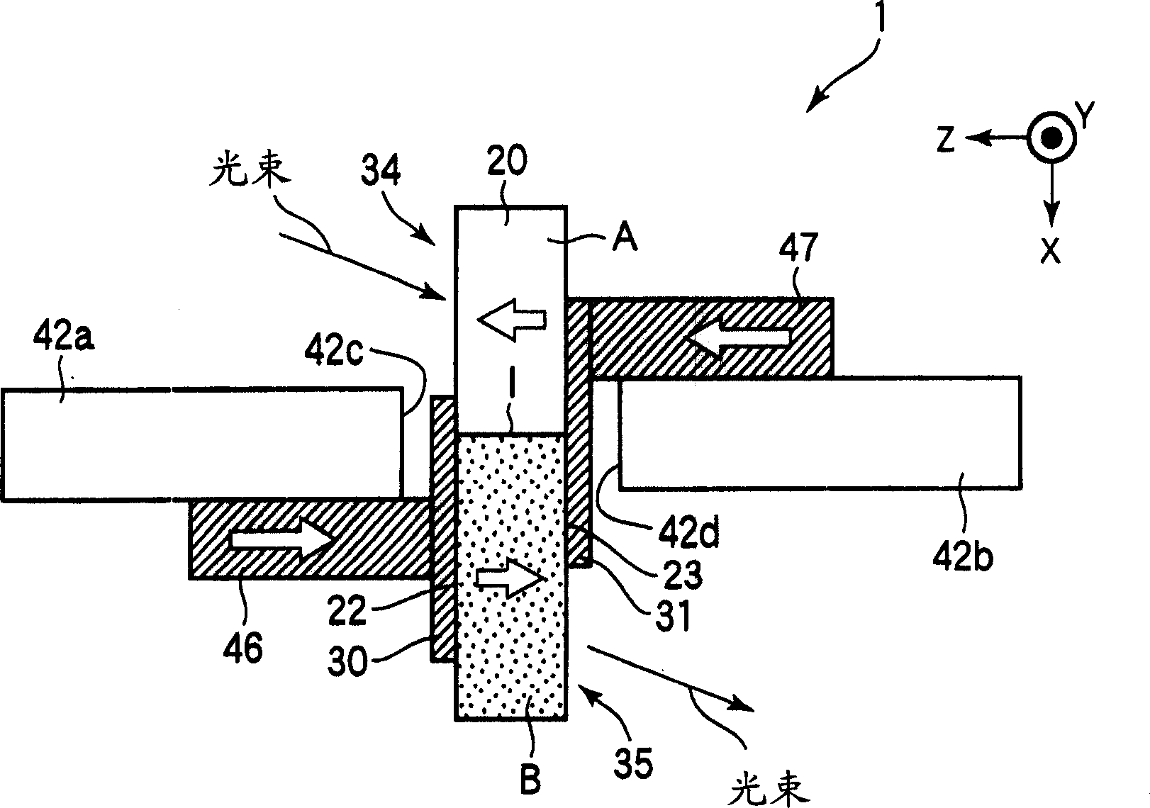
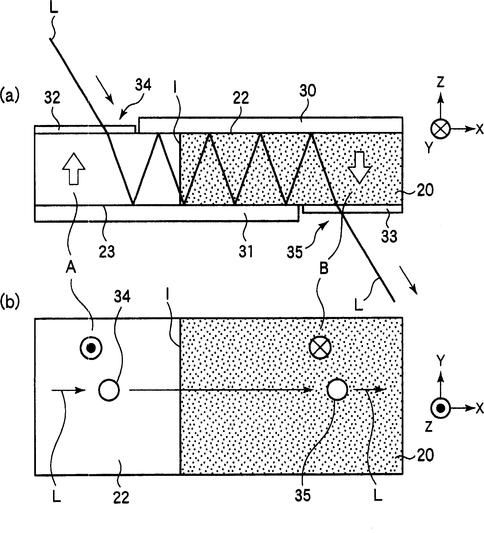
[0077] use now figure 1 and figure 2 The magneto-optical optical component according to the first embodiment of the present invention will be described. figure 1 Showing the structure of the magneto-optical optical component 1 of the present embodiment, figure 2 The structure of main parts of the magneto-optical optical component 1 is shown. here, in figure 1 and figure 2 Among them, the advancing direction of the light beam projected in the plane parallel to the light incident surface of the magneto-optical crystal of the magneto-optical optical component 1 is set as the X axis, and the direction perpendicular to the X axis in the plane is set as the Y axis. . And the Z axis is selected as the direction perpendicular to the light incident and exit planes. figure 1 Represents the structure of the magneto-optical optical component 1 viewed along the -Y direction, figure 2 (a) shows the structure of the main part of the magneto-optical optical component 1 viewed a...
no. 2 Embodiment approach
[0089] Refer below Figure 3 to Figure 18 A magneto-optical optical component according to a second embodiment of the present invention will be described. First, problems that may occur in the magneto-optical optical component 1 of the first embodiment described above will be described.
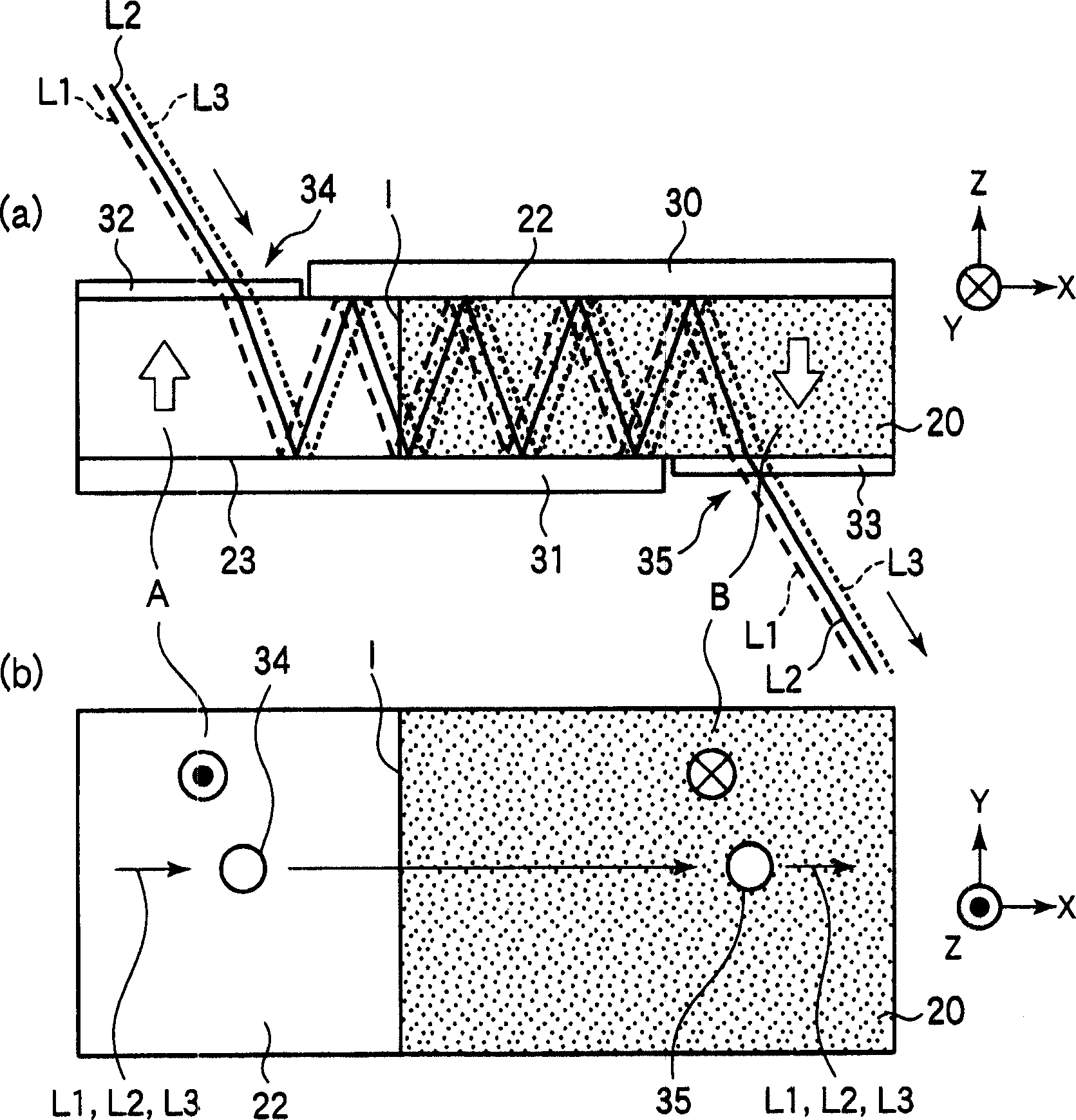
[0090] image 3 and figure 2 Correspondingly, it represents the optical path of the transmitted light in the Faraday rotator 20 of the magneto-optical optical component 1 . exist image 3 neutralize figure 2 Differently, considering the beam diameter of the light, the figure shows the optical path L2 (solid line) on the central axis of the light beam as approximately parallel light, the optical path L1 (long dotted line) shifted from the optical path L2 to the -X direction, and the optical path L1 (long dotted line) from the optical path Optical path L3 (short dashed line) shifted from L2 to the +X direction. Such as image 3 As shown, in the magneto-optical optical component 1 of th...
Embodiment 2-1
[0105] Now, the magneto-optical optical component of Example 2-1 of the present embodiment will be described. Figure 9 The configuration of main parts of the polarization controller 2 of this embodiment is shown. exist Figure 9 in, with figure 1 and figure 2 Construct the coordinate system similarly. Such as Figure 9 As shown, the polarization control body 2 has a magnetic yoke 42 (in Figure 9 Only the ends 42a and 42b) and the electromagnet of the coil wound on the yoke 42 are shown. One end portion 42 a of the yoke 42 is disposed close to the back surface of the total reflection film 30 such that the top end surface 42 c faces the back surface of the total reflection film 30 . The other end portion 42 b of the yoke 42 is disposed close to the back surface of the total reflection film 31 such that the top end surface 42 d faces the back surface of the total reflection film 31 . The distal end surface 42c of the end portion 42a and the distal end surface 42d of th...
PUM
 Abstract
Description
Claims
Application Information
 - R&D
- Intellectual Property
- Life Sciences
- Materials
- Tech Scout
- Unparalleled Data Quality
- Higher Quality Content
- 60% Fewer Hallucinations
Browse by: Latest US Patents, China's latest patents, Technical Efficacy Thesaurus, Application Domain, Technology Topic, Popular Technical Reports.
© 2025 PatSnap. All rights reserved.Legal|Privacy policy|Modern Slavery Act Transparency Statement|Sitemap|About US| Contact US: help@patsnap.com