
Method of mounting condenser microphone on main PCB and condenser microphone adapted for the same

A technology of microphones and capacitors, applied in electrostatic transducer microphones, printed circuits connected with non-printed electrical components, electric heating devices, etc., can solve problems such as difficulty in installing the main PCB and poor sound quality.

Inactive Publication Date: 2005-05-11
BSE CO LTD
View PDF0 Cites 12 Cited by
  • Summary
  • Abstract
  • Description
  • Claims
  • Application Information

AI Technical Summary

Problems solved by technology

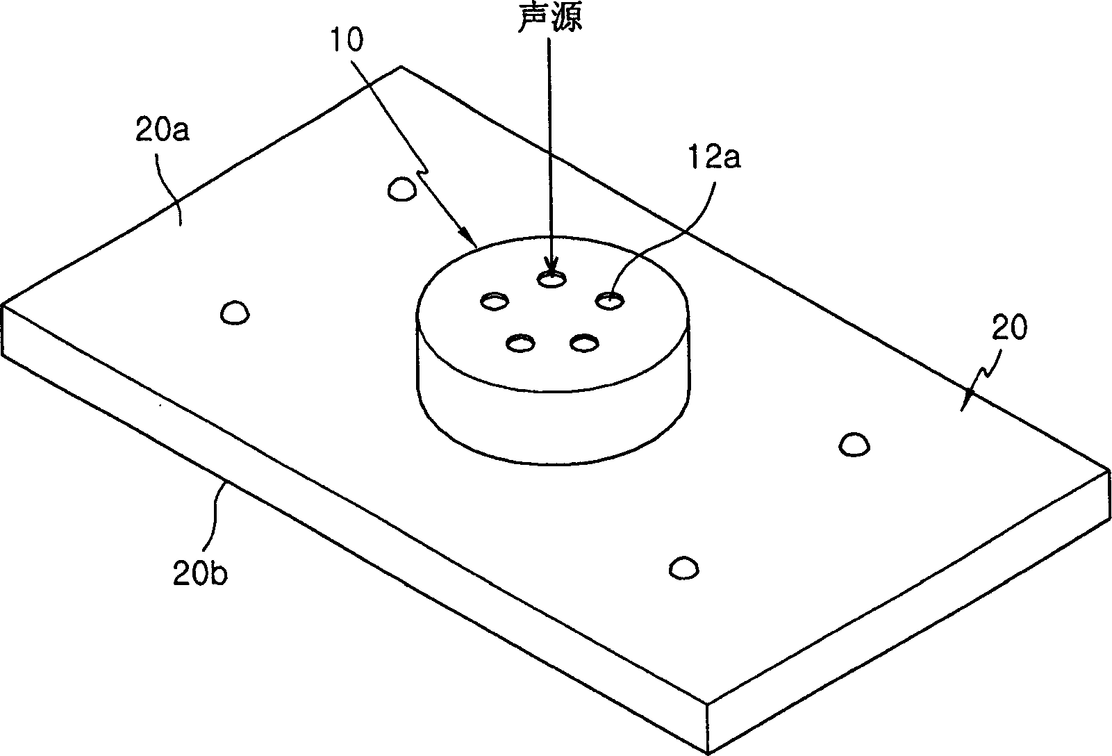
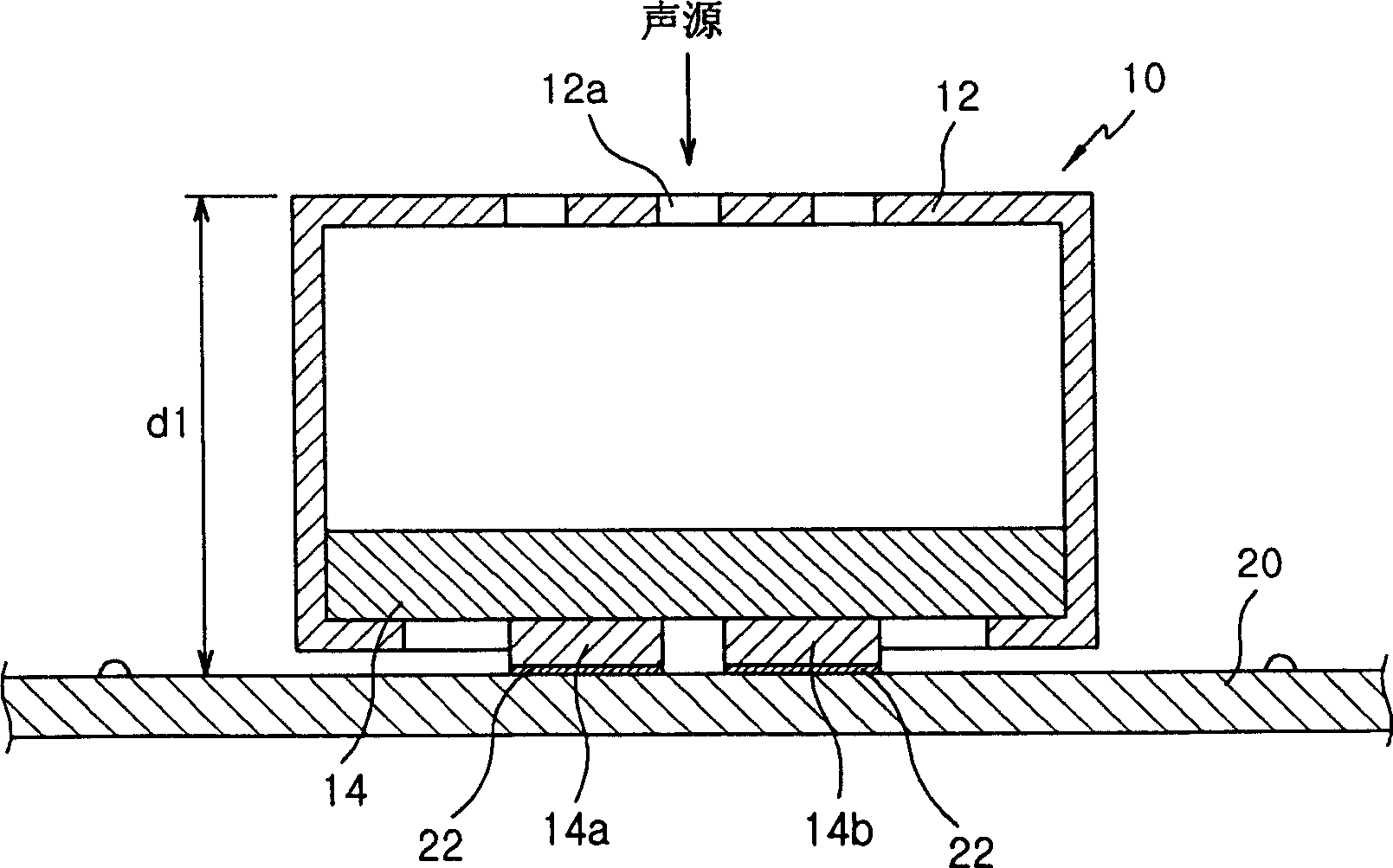
[0004] However, in a conventional condenser microphone, it is difficult to install the main PCB so that its front surface faces away from the sound source, that is, the front surface faces the inner space of the housing of the condenser microphone, because the housing Body has such Figure 1A and 1B sound hole shown
If the front surface of the main PCB is installed in the direction away from the sound source, the sound quality will be deteriorated because the sound wave transmission path increases

Method used


Image

  • Method of mounting condenser microphone on main PCB and condenser microphone adapted for the same
  • Method of mounting condenser microphone on main PCB and condenser microphone adapted for the same
  • Method of mounting condenser microphone on main PCB and condenser microphone adapted for the same

Examples


no. 1 example

[0032] Figure 4is a side sectional view of a condenser microphone suitable for the present invention. The condenser microphone 400 includes: a barrel-shaped housing 402 whose bottom surface is closed and the surface opposite to the bottom surface is open; an insulating ring 404 made of heat-resistant material and inserted into the housing 402 to protect internal components so as not to be damaged by heat; and a PCB 418 which is formed with an acoustic hole 418a and on which integrated circuits (ICs) and MLCCs (multilayer ceramic capacitors) are mounted. Inside the insulating ring 404 are placed a first barrel-shaped metal ring 406 , a backplate 408 , a gasket 410 , a diaphragm 412 , a polar ring 414 and a second barrel-shaped metal ring 416 .

[0033] refer to Figure 4 , the rear plate 408 contacts and is supported by the bottom surface of the casing 402 through the first metal ring 406 . Diaphragm 412 is supported towards PCB 418 by pole ring 414 and second metal ring 41...

no. 2 example

[0041] Figure 5 is a side sectional view of a condenser microphone suitable for the present invention. Such as Figure 5 As shown, the condenser microphone 500 includes: a housing 502 having a closed bottom surface and an open surface opposite the bottom surface; an insulating ring 504 made of a heat-resistant material and inserted into the housing 502; and an integrated base ring 516. Metal ring 506 , back plate 508 , washer 510 , diaphragm 512 and pole ring 514 are all placed inside insulating ring 504 . Insulation ring 504 and pole ring 514 are supported by integrated base ring 516 towards PCB 518 . The diaphragm 512 and the pole ring 514 can be manufactured integrally. A conductive layer 516 a is formed on the inner circumference of the integrated base ring 516 for electrically connecting the diaphragm 512 and the PCB 518 through the pole ring 514 . The PCB 518 is formed with an acoustic hole 518a, and a plurality of components (IC, MLCC) are mounted thereon.


PUM


Abstract

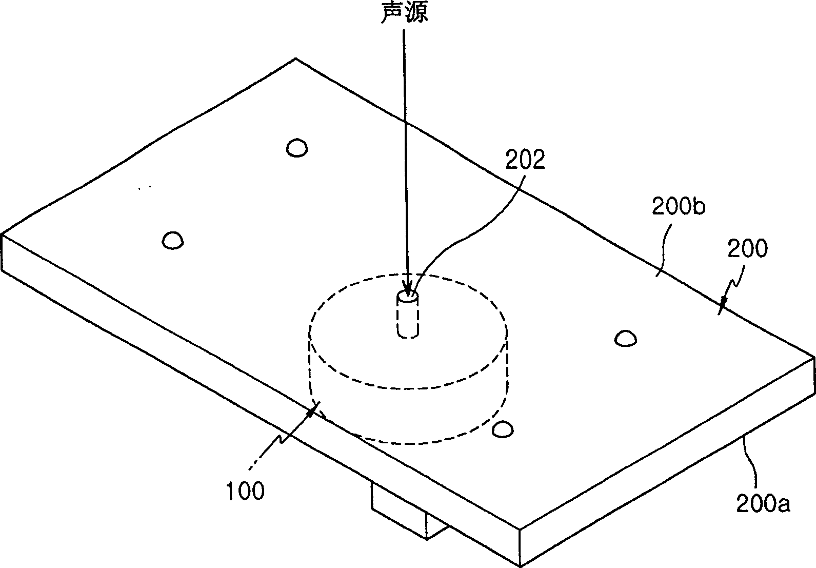
Provided are a condenser microphone and a method for installing the condenser microphone on a main PCB. The method includes the steps of assembling the components of a condenser microphone in such a manner that a condenser microphone is assembled such that a vibrating plate including a pair of vibrating modes and a rear plate faces an open surface of a housing of the condenser microphone, the housing having There is a closed bottom surface and an open surface opposite to the closed bottom surface, the PCB with the sound hole is installed on the housing, and the open surface of the housing is curled so that the connection end of the PCB protrudes relative to the curled surface; the assembly The final condenser microphone is placed on the main PCB so that the sound hole of the PCB of the condenser microphone corresponds to the through hole formed on the main PCB; and the connecting end of the condenser microphone is soldered to the platform of the main PCB. According to the present invention, if necessary, the main PCB can be mounted with its component surface facing the inside of the electronic product, thereby maintaining good sound quality by benefiting from a short sound wave transmission path.

Description

field of invention [0001] The present invention relates to a method of mounting a capacitor microphone, and more particularly to a method of mounting a capacitor microphone on a main printed circuit board (PCB) and a capacitor microphone suitable for the method. Background technique [0002] Often, customers expect electronic products to be functional and compact. Manufacturers of electronic products have thus gone to great lengths to make smaller products to meet this demand. Surface mount technology (SMT) can be used to miniaturize products, but SMT cannot be used for components with poor temperature resistance because high temperatures are applied to components during surface mount device (SMD) reflow. [0003] In addition, when it is assumed that SMT is used, during PCB mounting, it is necessary to orient the front surface of the main PCB on which components are mounted toward the inward direction of the electronic product in consideration of the thickness of the compon...

Claims


Application Information

Patent Timeline
Patent Type & Authority Applications(China)
IPC IPC(8): H04R1/06H04R1/08H04R19/00H04R19/01H04R19/04H05K1/18
CPCH04R1/06H04R1/083H04R19/00H05K1/181H05K2201/09072H05K2201/10083Y02P70/50H04R19/04
Inventor 宋清淡郑益周金贤浩
Owner BSE CO LTD
Learn More