Leading type water pressure overflow valve

A pilot valve, relief valve technology, applied in valve devices, safety valves, balance valves, etc., can solve the problems of pilot valve lateral vibration, noise and working stability are not well solved, and reduce leakage. and wire drawing erosion, small friction coefficient, and the effect of improving work stability

Inactive Publication Date: 2005-05-25
HUAZHONG UNIV OF SCI & TECH
View PDF0 Cites 22 Cited by
  • Summary
  • Abstract
  • Description
  • Claims
  • Application Information

AI Technical Summary

Problems solved by technology

However, the structure of the pilot valve is the same as that of the oil pressure relief valve, so the problems of lateral vibration, noise and working stability of the pilot valve have not been well solved

Method used


Image

  • Leading type water pressure overflow valve
  • Leading type water pressure overflow valve
  • Leading type water pressure overflow valve

Examples


Embodiment Construction

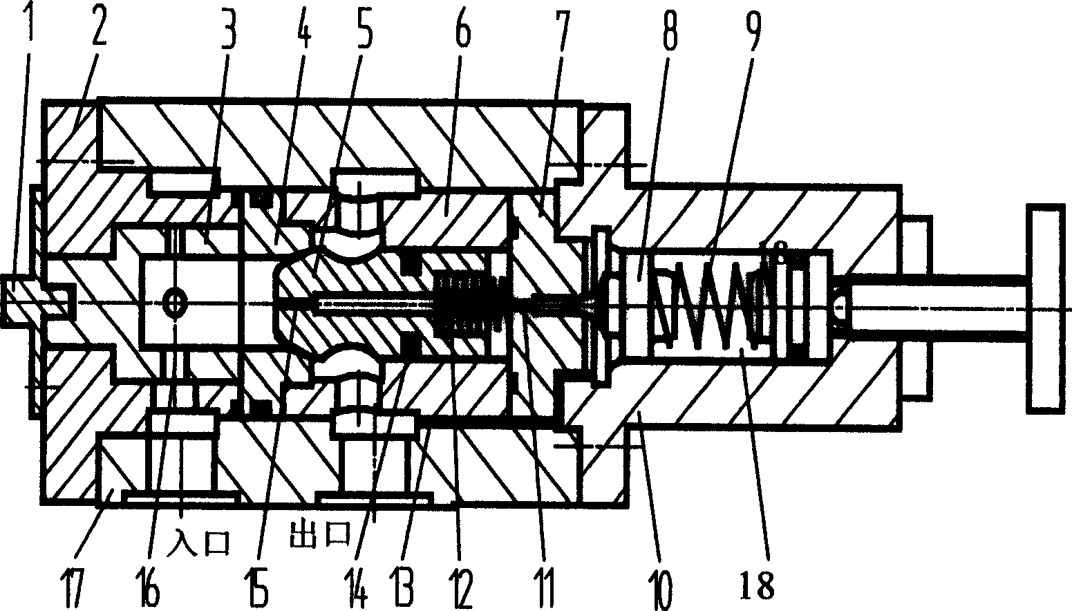
[0027] figure 1 As shown, an embodiment of the present invention includes: pressure adjustment knob 1, front end cover 2, throttle ring 3, throttle hole 16, main valve body 17, main valve seat 4, main valve core 5, rubber-plastic combination Seal 14, main valve damping hole 15, main valve sleeve 6, main valve spring 12, pilot valve seat 7, pilot valve damping hole 11, pilot valve core 8, pressure regulating spring 9, pilot valve body 10. The pilot valve and the main valve are fixed on the main valve body 17 through the pilot valve body 10 and connected coaxially, the pilot valve seat 7 presses the main valve spring 12, the main valve is a cone valve structure, and the pilot valve can adopt a cone valve or ball valve structure .

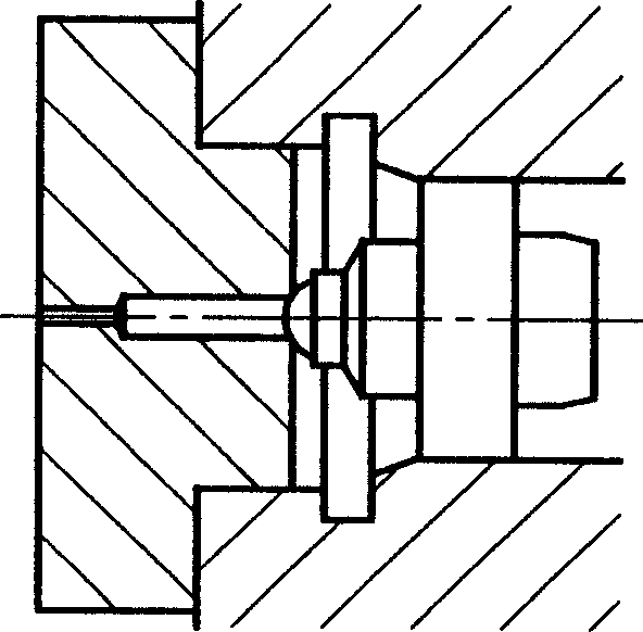
[0028] figure 2 Indicates an implementation state in which the pilot valve is a ball valve structure.

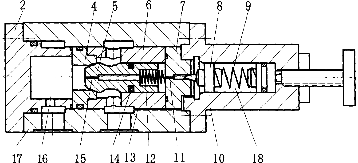
[0029] image 3 Represents another embodiment of the present invention. When there is only one throttle hole on the throttle ring, the thrott...


PUM


Abstract

The present invention relates to a pilot type hydraulic overflow valve. Its main valve body has front end cover, in said main valve body a main valve seat, a main valve buckle, a main valve core and a main valve spring are set, and said pilot valve is formed from its valve seat, valve core and pressure-regulating spring, said pilot valve is connected with said main valve. Said invention also provides the structure of main valve and pilot valve, and provides the application range of said valve.

Description

technical field [0001] The invention belongs to the category of valves, in particular to a pilot overflow valve, which is suitable for use as a pressure control element in hydraulic systems of water and water-based media. Background technique [0002] The water pressure relief valve is a commonly used pressure control element in the water (water-based) medium hydraulic transmission system. It can be used as a constant pressure relief valve to set the working pressure of the system or a safety valve for the safety protection of the system. Due to the characteristics of high vaporization pressure of media such as seawater, fresh water or high water base, when the hydraulic pressure relief valve works at a higher pressure, the flow velocity at the valve port is very high, and the partial pressure of the flow field at the valve port will be lower than that of water. Vaporization pressure, water vaporization produces a large number of bubbles, which is the cavitation phenomenon. ...

Claims


Application Information

Patent Timeline
Patent Type & Authority Applications(China)
IPC IPC(8): F16K17/10
Inventor 贺小峰李壮云朱玉泉朱碧海刘银水
Owner HUAZHONG UNIV OF SCI & TECH
Why Eureka
Try Eureka