Rotative drill rig in punching and smashing type
A drilling rig and drill pipe technology, which is applied to the driving device of rotary combined drilling, drilling equipment, earth-moving drilling, etc.
- Summary
- Abstract
- Description
- Claims
- Application Information
AI Technical Summary
Problems solved by technology
Method used
Image
Examples
Embodiment 1
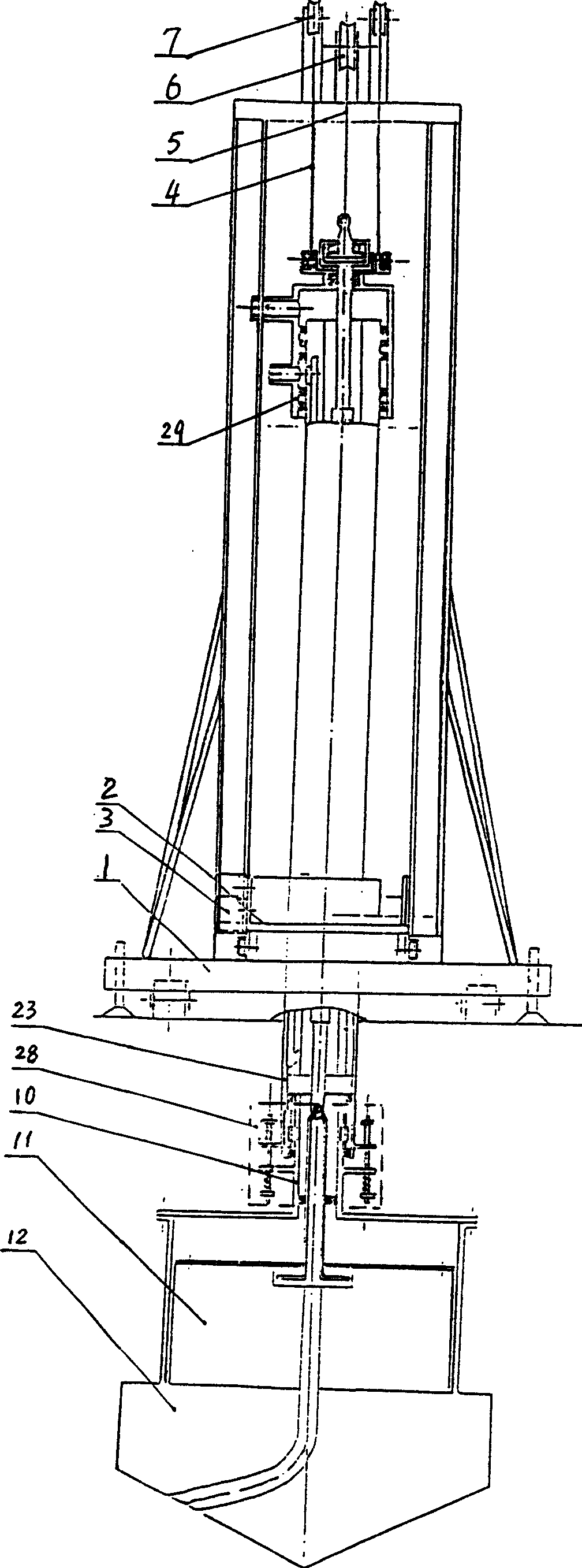
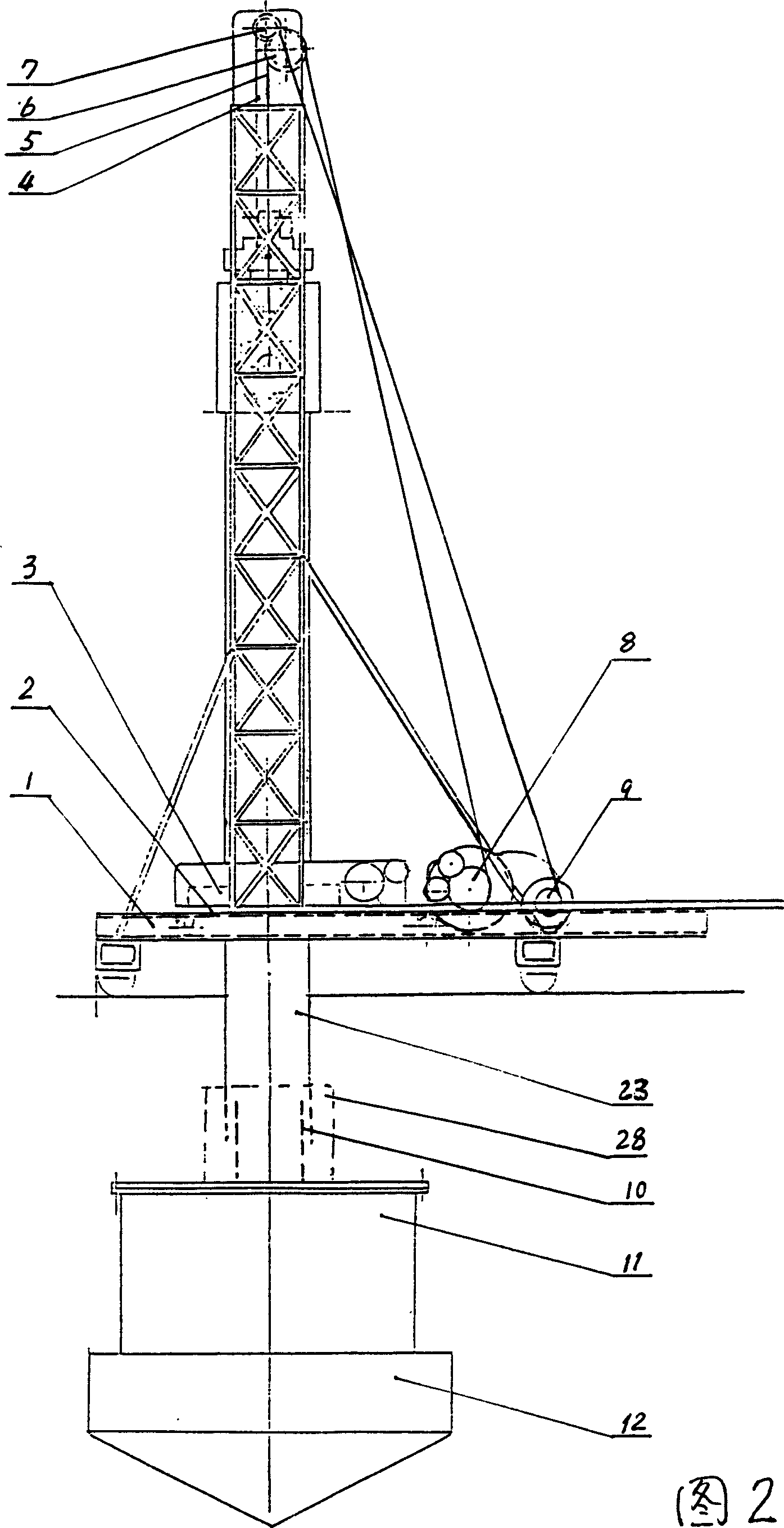
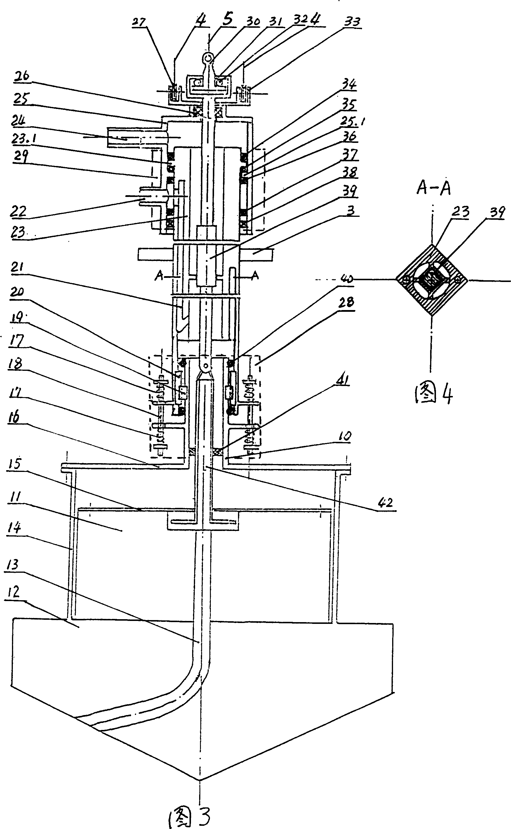
[0066] like figure 1 As shown in Figure 2, Figure 3, Figure 4, the rotary punching drilling rig according to the present invention is an inner pulling rod type rotary punching drilling rig driven by an inner pulling rod or an impact hammer, which includes a gas lift channel 21 in the processing In the tubular drill rod 23, a pull rod 39 is installed, the top of the pull rod 39 is a frame-like pull rod frame 31, and the pull rod frame 31 is equipped with a lifting rod 30 with a reel. There is a bearing 32, the lifting rod 30 protrudes upward from the upper wall hole of the tie rod frame 31, is connected to the wire rope 5, and is connected to the hoist 8 through the large sky wheel 6; the lower part of the tie rod 39 is connected with a tubular pull rod connecting rod 42, and the pull rod connecting rod 42 extends into the hammer cover 14 fixedly connected with the drill bit 12 processed with the mud water injection hole 13 , and movably connected with the annular hammer head 1...
Embodiment 2
[0072] like figure 1 As shown in Figure 2, Figure 5, Figure 6, the rotary punching drilling rig according to the present invention is an outer pulling rod type rotary punching drilling rig driven by an outer pulling rod or an impact hammer, which is included outside the drill rod 23 and is provided with Two (or more than two) bolt-shaped tie rods 43 and the lifting rod 48 matched with it, the upper end of the tie rod 43 is located under the machine base 2, and passes downward through the annular cover plate 47, the annular support The plate 45 and the hole of the driving rotary plate 44 fixedly connected with the drill rod 23 are connected with the annular hammer head 11 located on the top of the drill bit 12 and outside the drill rod connecting rod 10 . A slurry suction and water injection hole 13 is machined in the drill bit 12 . The drill rod connecting rod 10 fixedly connected with the drill bit 12 is connected with the drill rod 23 with the gas lift channel 21 processed ...
Embodiment 3
[0077] like figure 1 As shown in Fig. 2 and Fig. 7, the rotary punching drilling rig according to the present invention is an inertial force vibration impact rotary punching drilling rig with a submersible inertial force exciter vibration and impact hammer head. Above the drill bit 12 of the water injection hole 13, the symmetric submersible inertial force exciter outside the vibration damping device 28 vibrates the impact hammer 49, and its cable 50 passes through the cable channel 52 in the drill pipe 23, and passes through the drill pipe 23 and The cable slip ring device 51 between the machine bases 2 is connected to the power supply; the drill pipe 23 processed with the gas lift channel 21 upwards passes through the anti-twist device 29, the drill pipe lifting wheel base 33, the drill pipe lifting wheel 27, the wire rope 5, the large The sky wheel 6 is connected with the hoist 8, and is connected downward through the vibration damping device 28 and the drill rod connecting...
PUM
 Abstract
Description
Claims
Application Information
 - R&D
- Intellectual Property
- Life Sciences
- Materials
- Tech Scout
- Unparalleled Data Quality
- Higher Quality Content
- 60% Fewer Hallucinations
Browse by: Latest US Patents, China's latest patents, Technical Efficacy Thesaurus, Application Domain, Technology Topic, Popular Technical Reports.
© 2025 PatSnap. All rights reserved.Legal|Privacy policy|Modern Slavery Act Transparency Statement|Sitemap|About US| Contact US: help@patsnap.com


