
High frequency oscillator

A high-frequency oscillator and high-frequency oscillator circuit technology, applied in power oscillators, electrical components, etc., can solve the problems of oscillation frequency deviation, constant L component of the Neckel Pitzer oscillator, and conductor damage, etc. The effect of stabilizing the oscillation frequency

Active Publication Date: 2005-06-22
MURATA MFG CO LTD
View PDF3 Cites 4 Cited by
  • Summary
  • Abstract
  • Description
  • Claims
  • Application Information

AI Technical Summary

Problems solved by technology

Therefore, it is difficult to keep the L component of the Colpitts-type oscillator constant, which causes fluctuations in the oscillation frequency
[0019] In addition, since part of the wiring electrode pattern of the oscillator is formed from the front surface of the substrate to the back surface, the wiring pattern is extended, the conductor is damaged, and the C / N characteristic of the oscillation signal is deteriorated.
[0020] In addition, since the rear side is assembled close to the module substrate on which the voltage controlled oscillator is mounted, electrical coupling occurs through the ground electrode and the electrode formed on the module substrate, and after the constant of the Colpitts type oscillator changes, Possibility of oscillation frequency variation
In addition, the noise from the module substrate is transmitted to the ground electrode on the back, which may affect the oscillation signal

Method used


Image

  • High frequency oscillator
  • High frequency oscillator
  • High frequency oscillator

Examples


Embodiment Construction

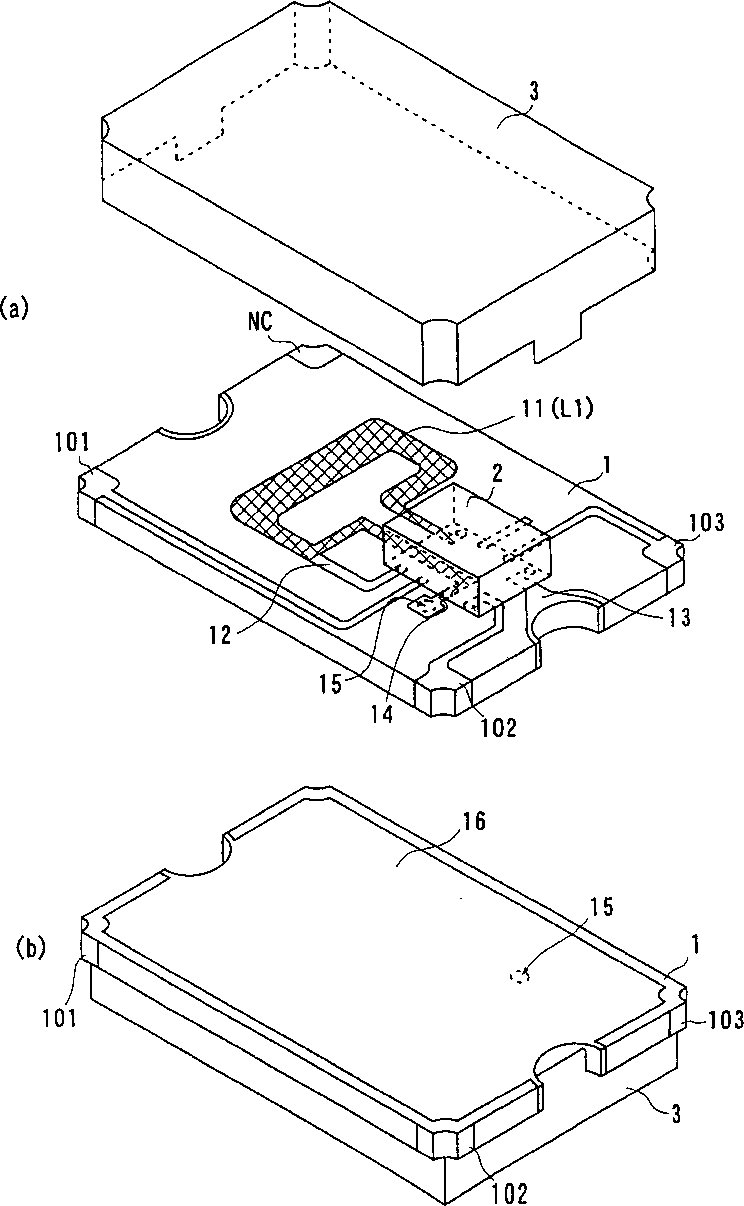
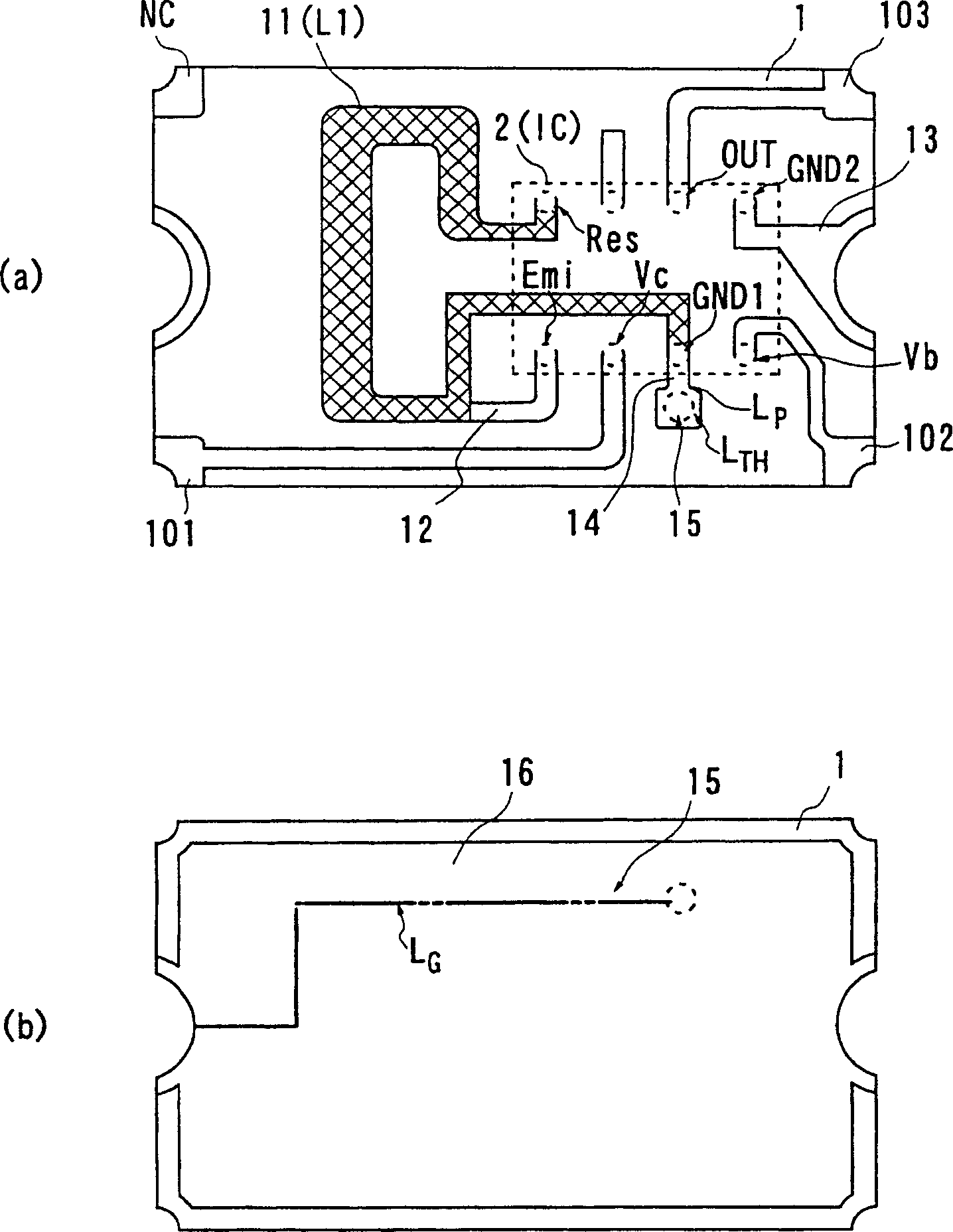
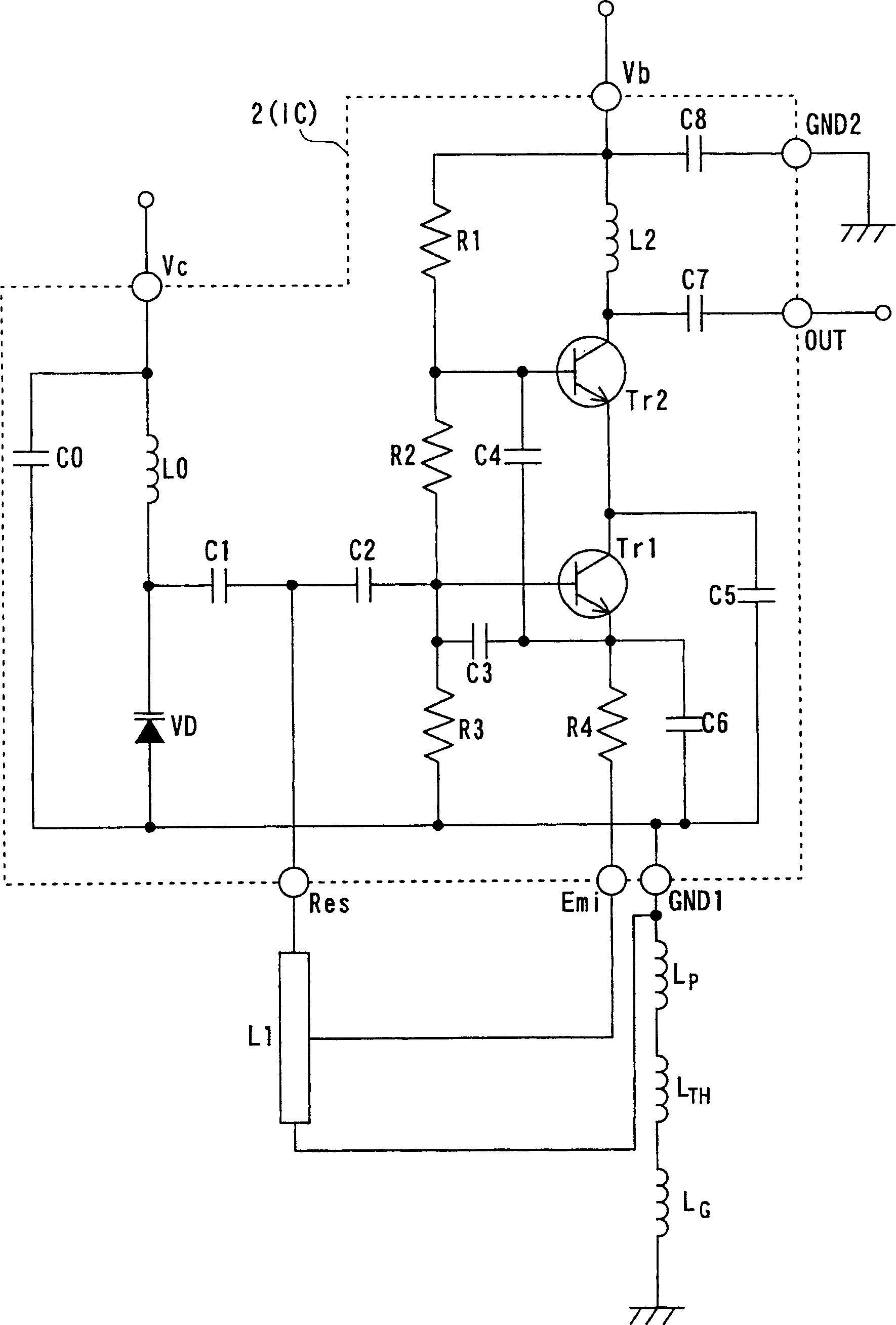
[0038] Below, refer to Figure 1 ~ Figure 3 , the high-frequency oscillator according to the first embodiment of the present invention will be described. In addition, in this embodiment, a voltage-controlled oscillator will be described as an example of a high-frequency oscillator.

[0039] figure 1It is a perspective view showing the schematic structure of the voltage controlled oscillator of this embodiment, (a) is a perspective view from the IC chip mounting surface side, (b) is a perspective view from the side opposite to (a).

[0040] also, figure 2 (a) is figure 1 A top view of the substrate of the voltage controlled oscillator shown, figure 2 (b) is a bottom view of the substrate.

[0041] also, image 3 It is an equivalent circuit diagram of the voltage controlled oscillator of this embodiment.

[0042] In addition, in the following, in order to simplify the description, the figure 2 The surface shown in (a) is referred to as the surface of the dielectric ...


PUM


Abstract

To provide a high-frequency oscillator having a stable oscillation frequency with an excellent C / N characteristic. On the surface of a dielectric substrate 1, a plurality of lands on which IC chips 2 are mounted are formed in an array, and also a resonator electrode pattern 11 is formed. Furthermore, on the rear face of the dielectric substrate 1, a grounding electrode 16 is formed on the substantially entire face. One end of the resonator electrode pattern 11 is connected to a land on which a resonator connection terminal (Res terminal) of the IC chip 2 is mounted. The other end of the resonator electrode pattern 11 is connected to a land on which a grounding terminal (GND1 terminal) of an oscillating transistor in the IC chip 2 is mounted. The land which the GND1 terminal is mounted on, and also the resonator electrode pattern is connected to, conducts to the grounding electrode 16 formed on the rear face, through a wiring electrode pattern 14 and a through hole 15.

Description

technical field [0001] The present invention relates to a high-frequency oscillator that oscillates a predetermined high-frequency signal, and in particular to a resonator in which the main part of an oscillating circuit is formed into an IC chip, and the IC chip is connected to a substrate on which the IC chip is assembled. A high-frequency oscillator is formed. Background technique [0002] Conventionally, high-frequency oscillators, such as voltage controlled oscillators, consist of a resonator that resonates at a predetermined frequency determined by an applied control voltage, and an oscillation circuit connected to the resonator that amplifies a signal at the resonant frequency and oscillates. As a voltage controlled oscillator configured in this way, there is a circuit configuration disclosed in Patent Document 1. [0003] As a structure for realizing this circuit configuration, as disclosed in Patent Document 2, there is a structure in which a resonator electrode pa...

Claims


Application Information

Patent Timeline
Patent Type & Authority Applications(China)
IPC IPC(8): H03B5/18H03B5/02H03B5/12
CPCH03B5/1206H03B5/1243H03B5/1847H03B2201/0208
Inventor 秦俊夫佐藤文俊
Owner MURATA MFG CO LTD
Learn More