Integrator

a technology of integrated circuits and integrated circuits, applied in the field of integrated circuits, can solve the problems of unfavorable low voltage use of circuits for reducing power consumption, unfavorable low voltage use, etc., and achieve the effects of low power consumption, low complexity, and stable oscillation frequency

Inactive Publication Date: 2012-06-07
ST ERICSSON SA
View PDF4 Cites 4 Cited by
  • Summary
  • Abstract
  • Description
  • Claims
  • Application Information

AI Technical Summary

Benefits of technology

[0020]The amplification and phase shifting element can comprise at least one further signal path including one or more parallel-coupled inverters coupled in parallel to one or more of the inverters of the first plurality of inverters of the first signal path. This feature provides flexibility in selecting an embodiment of the integrator having desired amplification and phase shift characteristics.
[0021]At least one of the further signal paths can include a phase shifting network. This feature provides flexibility in selecting an embodiment of the integrator having desired phase shift characteristics, a stable oscillation frequency, low complexity and low power consumption. In particular, the phase shifting network may be passive.
[0022]The integrator can be adapted to receive the input signal in a differential format and to deliver the oscillation signal in a differential format. Correspondingly, the method can comprise receiving the input signal in a differential format and delivering the oscillation signal in a differential format. Such a format can provide enhanced noise immunity.
[0023]In one embodiment, the means for amplification and the means for providing a phase shift may be provided as an amplification and phase shifting element, wherein the amplification and phase shifting element is adapted for processing the oscillation signal in a differential format and the amplification and phase shifting element may comprise: a differential input having a first differential component input and a second differential component input; a differential output having a first differential component output and a second differential component output; a first signal path having a first plurality of inverters coupled in series between the first differential component input and the first differential component output; a second signal path having a second plurality of inverters coupled in series between the second differential component input and the second differential component output; a first cross-coupled capacitive element coupled between the first differential component input and an output of one inverter of the second plurality of inverters; and a second cross-coupled capacitive element coupled between the second differential component input and an output of one inverter of the first plurality of inverters. This enables reduced power consumption by requiring less active circuitry.
[0024]At least one of the inverters can comprise a Standard Voltage Threshold (SVT) transistor. The use of an SVT transistor can reduce or obviate the need to use a High Voltage Threshold (HVT) or Low Voltage Threshold (LVT) process for low voltage operation, which can reduce the number of masks required for integrated circuit manufacture.
[0025]The series coupled capacitive element can comprise a series coupled resistive element. This feature can contribute to enhanced integrator performance at higher signal frequencies.

Problems solved by technology

Adaptation of conventional circuits to low power operation can cause undesirable restriction of the permitted range of signal voltage swing and undesirable increase in power consumption, due, for example, to the need to use folded cascoding for increasing gain.
Some circuits for reducing power consumption are impractical for use at low voltages.

Method used


Image

  • Integrator
  • Integrator
  • Integrator

Examples


Embodiment Construction

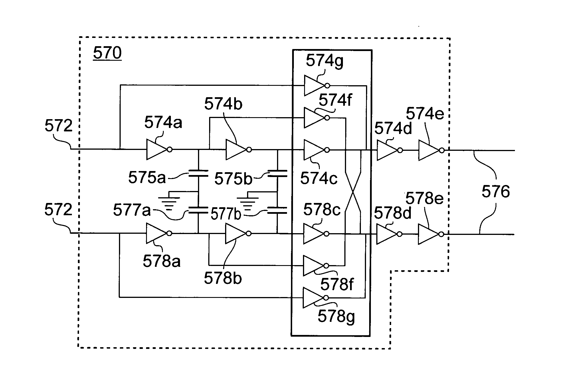
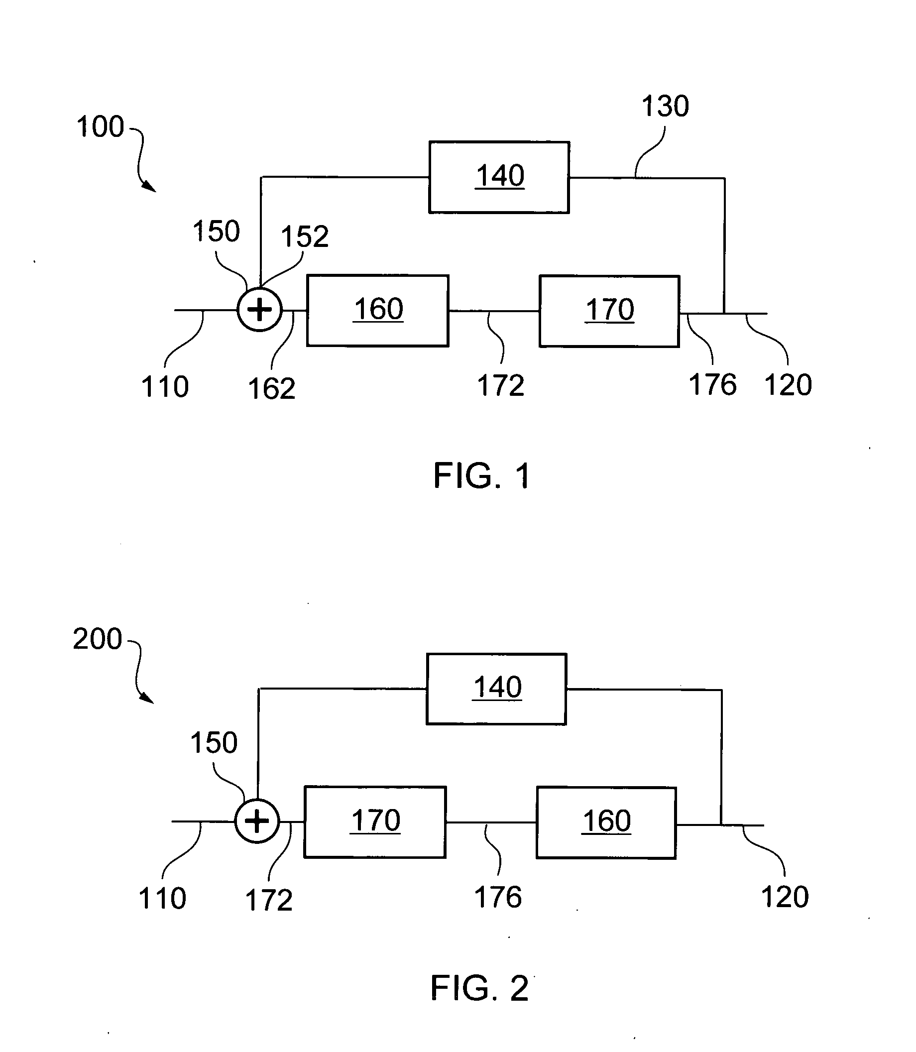
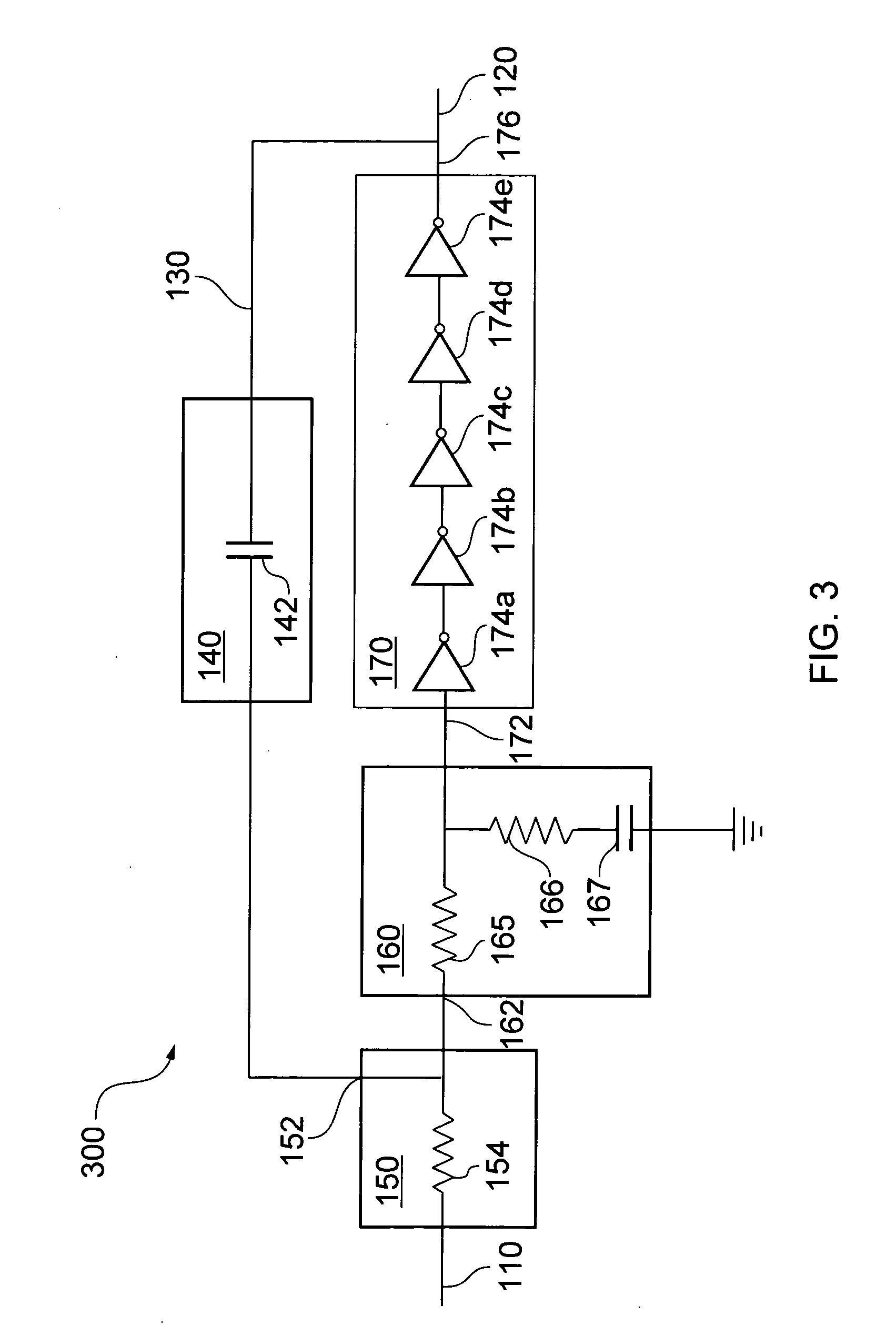
[0003]According to a first aspect there is provided an integrator comprising:

[0004]a loop operable to oscillate at an oscillation frequency, the loop comprising means for amplification, means for filtering and means for providing a phase shift;

[0005]a capacitive element series coupled in the loop;

[0006]means for summing into the loop an input signal having a bandwidth lower than the oscillation frequency; and

[0007]an output for an oscillation signal dependent upon an integral of the input signal.

[0008]According to a second aspect there is provided a method of integration comprising:

[0009]generating an oscillation at an oscillation frequency by providing amplification, filtering and phase shifting in a loop;

[0010]providing a capacitance series coupled in the loop;

[0011]summing into the loop an input signal having a bandwidth lower than the oscillation frequency; and

[0012]delivering from the loop an oscillation signal dependent upon an integral of the input signal.

[0013]Because the in...


PUM


Abstract

An integrator (100) comprises an amplification and phase shifting element (170) with a feedback path (130) forming a loop and comprising a capacitive element (140). An input signal is summed into the loop, and the loop is arranged to oscillate at an oscillation frequency higher than the frequencies of interest in the input signal. The loop includes a filter (160) for attenuating the oscillation signal to ensure that the amplification and phase shifting element (170) can provide amplification for the input signal. The input signal is integrated and the integrated signal perturbs the zero crossings of the oscillation signal.

Description

FIELD OF THE DISCLOSURE[0001]The disclosure relates to an integrator and a method of integration, to a device comprising one or more integrators, and to a mobile communication device comprising such a device.BACKGROUND TO THE DISCLOSURE[0002]Integrators have application in a wide range of electronic circuits, for example, analogue-to-digital converters, particularly sigma-delta analogue-to-digital converters, digital-to-analogue converters, and filters, particularly loop filters in control loops. In many electronic devices utilising such circuits, and particularly in mobile electronic devices, low voltage operation and low power consumption is important. Adaptation of conventional circuits to low power operation can cause undesirable restriction of the permitted range of signal voltage swing and undesirable increase in power consumption, due, for example, to the need to use folded cascoding for increasing gain. Some circuits for reducing power consumption are impractical for use at ...

Claims


Application Information

Patent Timeline
Patent Type & Authority Applications(United States)
IPC IPC(8): G06G7/184
CPCG06G7/18H03K7/06H03M3/452H03M3/43H03M3/448H03L7/24
Inventor PUTTER, BAS
Owner ST ERICSSON SA
Why Eureka
Try Eureka