Optical non-contact type narrow angle measuring device

A non-contact, measuring device technology, applied in the direction of measuring devices, optical devices, instruments, etc., can solve the problems of complex structure of the measuring system, limited installation space, large volume, etc., and achieve small size, high precision and simple structure Effect

Inactive Publication Date: 2005-06-29
TIANJIN UNIV
View PDF0 Cites 5 Cited by
  • Summary
  • Abstract
  • Description
  • Claims
  • Application Information

AI Technical Summary

Problems solved by technology

Although these methods can provide high measurement accuracy, the measurement system based on this design is relatively complex in structure, large in size, and limited in installation space, so it has great limitations in industrial practical applications, especially difficult to process Mechanical bonding for in-line measurement

Method used


Image

  • Optical non-contact type narrow angle measuring device
  • Optical non-contact type narrow angle measuring device
  • Optical non-contact type narrow angle measuring device

Examples


Embodiment Construction

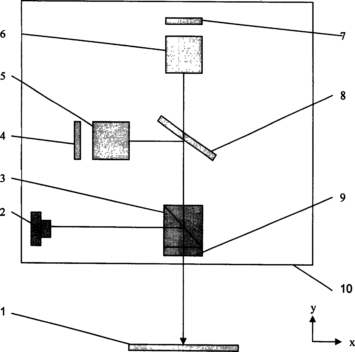
[0010] The optical non-contact small angle measuring device adopts the optical differential angle measuring device to detect the change of the rotation angle of the measured object. The process is: the semiconductor laser is integrated with the collimating lens to form 2 through the clamping frame, and the emitted light After passing through the polarizing beam splitter 3, the S polarized light in it is reflected and then passes through the 1 / 4 wave plate 9 to become circularly polarized light, which is incident on the surface of the object or the reflector 1 fixed on the surface of the measured object, and reflected from the measured reflecting surface Circularly polarized light, after passing through the beam splitter 9, becomes P polarized light, and then through the beam splitter 8, it is divided into two mutually orthogonal beams of equal energy. In 5 and 6, the intensity of the emitted light is detected by photodiodes 4 and 7, respectively. 2, 3, 4, 5, 6, 7, 8, and 9 are...


PUM


Abstract

This invention discloses an optics non-contact small angle measurement device, which belongs to small angle measurement technique. The device comprises optics probe, photo electricity test device and computer communication and control device, wherein; the optics probe comprises calibration semi-conductor laser, deflecting spectroscope, a quarter wave sheet, object surface or reflection mirror, spectroscope, inner reflection prism and photoelectricity diode. The optics and photoelectricity parts are fixed on the base plate. The photoelectricity test device comprises signal process unit and the computer communication and control device comprises single machine, digit filter, switch output end, upper machine communication port and display device.

Description

technical field [0001] The invention relates to an optical non-contact small-angle measuring device, which belongs to the small-angle measuring technology. Background technique [0002] At present, commonly used optical angle measurement methods include optical dividing head method, polygonal prism method, photoelectric encoding method, self-collimation method, Moiré fringe method, parallel interferogram method, circular grating method, laser interferometry and ring laser method. Wait. For small angle measurement (α≤1°, especially within ±10~20arcmin), the main measurement methods include laser small angle measuring instrument method, standard optical angle gauge method, circular grating angle measurement method, laser interferometry method, photoelectric automatic Collimator method. Although these methods can provide high measurement accuracy, the measurement system based on this design is relatively complex in structure, large in size, and ...

Claims


Application Information

Patent Timeline
Patent Type & Authority Applications(China)
IPC IPC(8): G01B11/26
Inventor 刘庆纲李志刚李德春胡小鹏田会斌
Owner TIANJIN UNIV
Why Eureka
Try Eureka