Atomic force microscope measuring device based on angular measurement

A technology of atomic force microscope and angle measurement device, which can be applied in measurement device, optical device, scanning probe microscopy, etc., and can solve problems such as measurement principle error

Inactive Publication Date: 2005-06-29
TIANJIN UNIV
View PDF0 Cites 7 Cited by
  • Summary
  • Abstract
  • Description
  • Claims
  • Application Information

AI Technical Summary

Problems solved by technology

Although this method is simple in structure and suitable for commercial production, in the scanning process of this type of microscope under the constant force mode, due to the change of the position of the fixed end of the probe, the error of the measurement principle is introduced. To obtain high-precision measurement results, it is necessary to Make error corrections or strict corrections

Method used


Image

  • Atomic force microscope measuring device based on angular measurement

Examples


Embodiment Construction

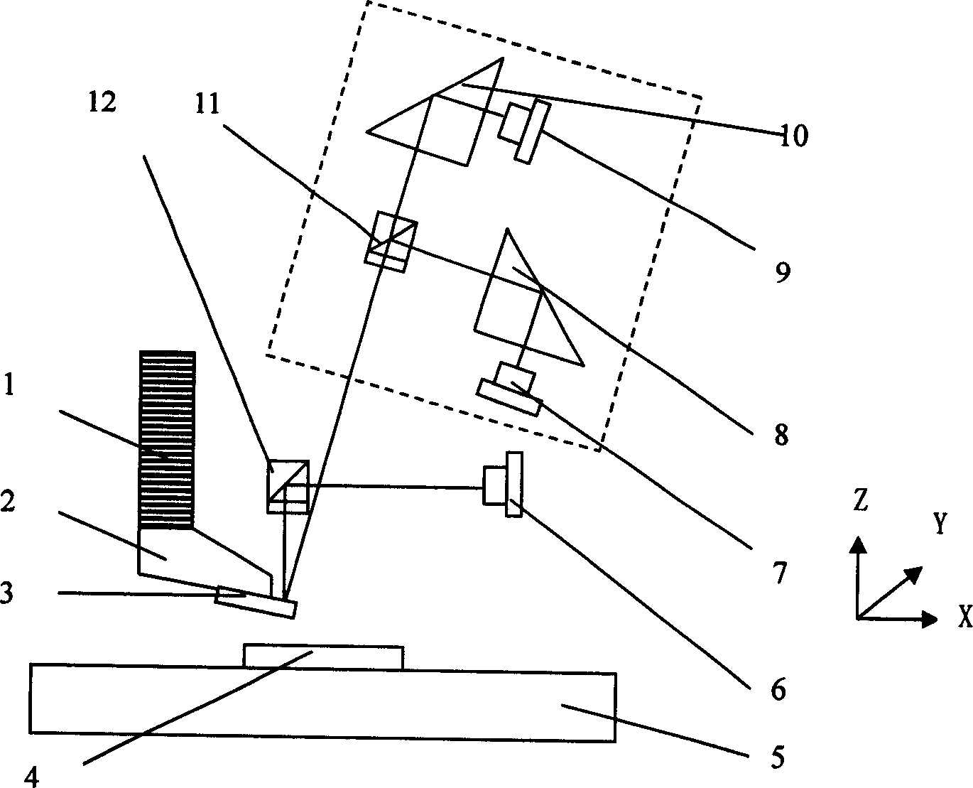
[0009] The AFM measurement method based on angle measurement, the angle change of the tip of the cantilever beam caused by the force change during the scanning process of the AFM probe, adopts the optical differential angle measurement device ( figure 1 inside the dotted line), the process is: the visible light emitted by the laser 6 is reflected by the polarizing beam splitter 12 after the converging lens, passes through the 1 / 4 wave plate, and is incident on the cantilever beam / AFM probe 3 reflective surface of the atomic force microscope, The laser reflected by the AFM probe carries the angle change information of the cantilever beam into the angle measurement device; the angle measurement device is fixed on the adjustable angle platform, which is fixed on the system base; when the initial force measurement is set, it can be It is considered that the output signal of the angle measuring device is "zero"; when the measuring force changes during the scanning process, the bendi...


PUM


Abstract

This invention discloses an atomic force microscope measurement method based on angle measurement, which belongs to the test system and device of the signals of atomic force microscope APM probe and cantilever. The said angle measurement device comprises calibration light source, focus lens, a quarter of wavelet, light splitter, two threshold prism, two photoelectricity diodes, Z-tracing micro-driver, two-dimensional micro-scanners in plane, probe clamper and APM probe. And the sample bench and the two-dimensional micro-scanner and APM probe and Z-tracing micro driver are separated with adjustable distance.

Description

technical field [0001] The invention relates to an atomic force microscope measurement device based on angle measurement, which belongs to a probe / cantilever beam signal detection system and device of an atomic force microscope (AFM). Background technique [0002] When the end of the cantilever beam is stressed, two deformations will occur at the end, one is deflection and the other is rotation angle. The atomic force microscope uses the probe at the tip of the micro-cantilever beam. When the probe approaches or touches the surface of the object to be measured, there will be a force interaction between the probe and the sample, and the force will cause the micro-cantilever beam to bend. Therefore, The change of the bending amount of the micro-cantilever can be detected in two ways, that is, measuring the change of the deflection of the micro-cantilever of the atomic force microscope, or measuring the change of the tip rotation angle of the micr...

Claims


Application Information

Patent Timeline
Patent Type & Authority Applications(China)
IPC IPC(8): G01B11/26G01B21/20G01Q60/24
Inventor 刘庆纲李志刚李德春匡登峰王璐李敏
Owner TIANJIN UNIV
Why Eureka
Try Eureka