
On-star once image surface calibration method for interference type super spectrum imager

An on-board calibration and hyperspectral technology, which is applied in the directions of using multiple reflections to generate spectra and spectrum generation, can solve the problems of mechanical failures in the background technology and low reliability of on-board calibration, and solve the problems of insufficient light source energy, Improve strength and achieve flexible effects

Inactive Publication Date: 2005-07-06
XI'AN INST OF OPTICS & FINE MECHANICS - CHINESE ACAD OF SCI
View PDF0 Cites 6 Cited by
  • Summary
  • Abstract
  • Description
  • Claims
  • Application Information

AI Technical Summary

Problems solved by technology

[0006] The invention solves the technical problems that the background technology is prone to mechanical failure and the reliability of on-board calibration is low

Method used


Image

  • On-star once image surface calibration method for interference type super spectrum imager
  • On-star once image surface calibration method for interference type super spectrum imager
  • On-star once image surface calibration method for interference type super spectrum imager

Examples


Embodiment Construction

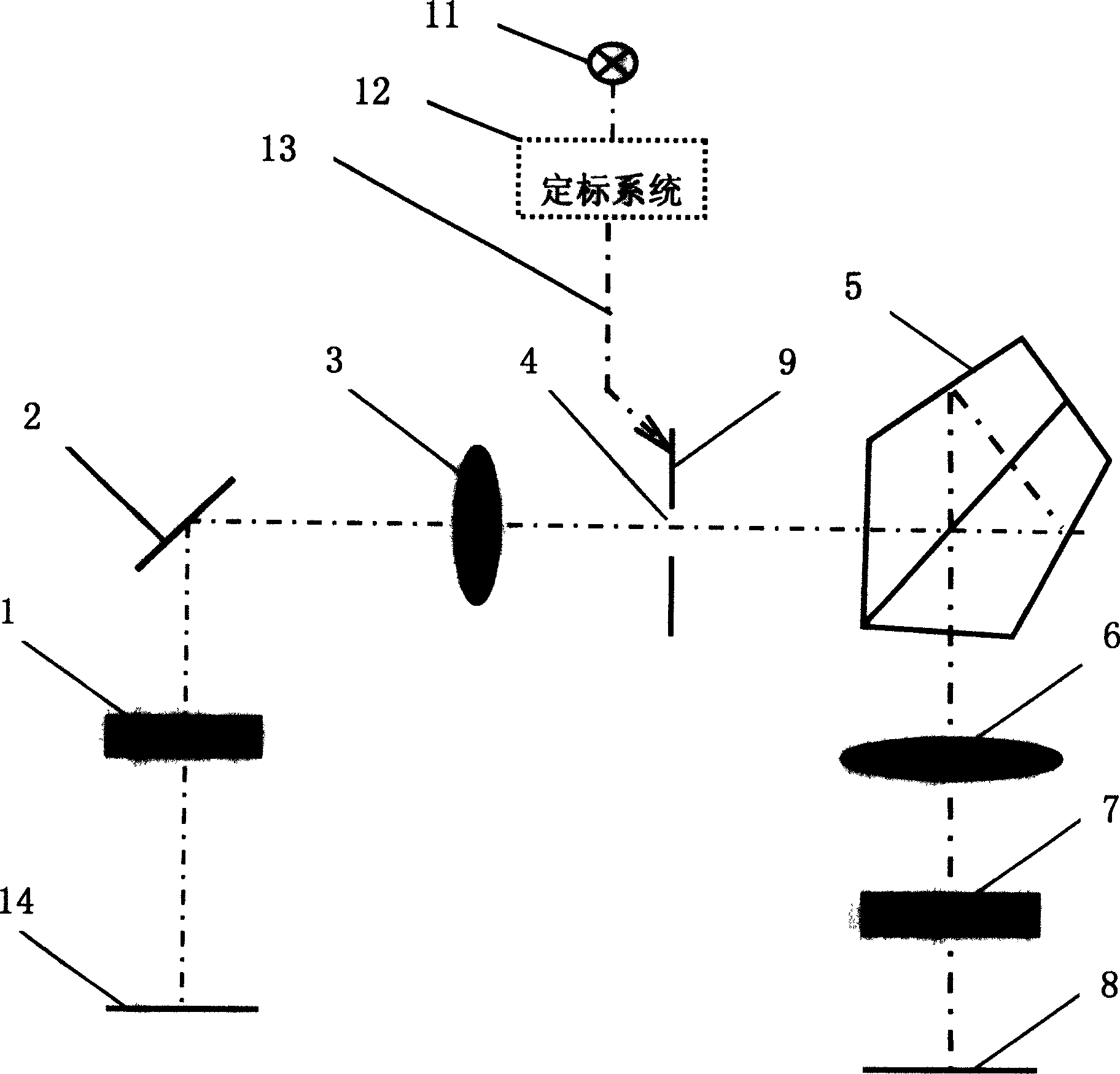
[0023] see figure 2 , the present invention utilizes the characteristics of the principle of the interferometric hyperspectral imager system, introduces a calibration light source 11 on the primary image plane 9, generates an interferogram on the detector image plane, that is, the secondary image plane 8, and realizes relative calibration on the star. Concrete implementation steps of the present invention are as follows:

[0024] 1. The calibration light source 11 passes through the calibration system 12 to generate calibration light 13 that can be imaged at the slit 4 . The position of the introduction point of the calibration light 13 can be any position on the primary image plane 9, which can be selected according to the conditions of the system structure. In order to improve the intensity of the interferogram and meet the requirements of the dynamic range of the detector response, the size of the area of ​​the calibration light 13 on the primary image plane can be select...


PUM


Abstract

This invention relates to interference super spectrum image apparatus one time plane scaling method, which uses the characteristics of the image system principle and introduces the scaling light source on the one time plane and generates interference graph on the detecting plane to realize the relative scaling. This invention solves the technique problems of mechanic faults and its scaling light source leading point's positions and sizes are selected according to the system structure conditions and detector responding dynamic range requirements.

Description

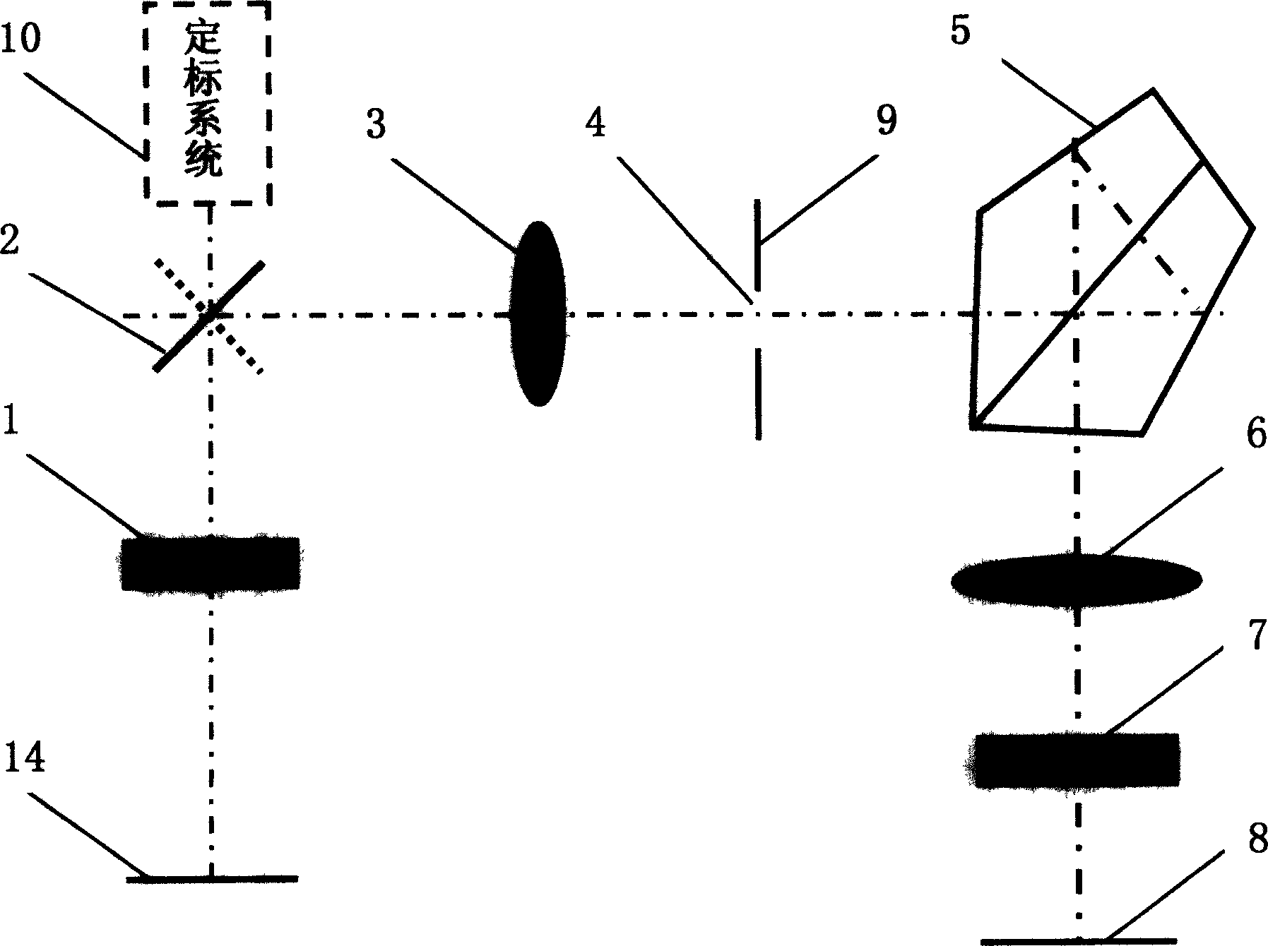
technical field [0001] The invention relates to a method for calibrating an interference spectrum imaging optical instrument for satellite remote sensing, in particular to a method for calibrating an image plane on a satellite of an interference type hyperspectral imager. Background technique [0002] The interferometric hyperspectral imager is an interferometric spectral imaging optical instrument for satellite remote sensing. For its principle, see figure 1 . The object light is imaged on the primary image plane 9, that is, the plane of the slit 4 through the swing mirror 2 and the front mirror 3, and forms a strip on the secondary image plane 8, that is, the plane of the CCD detector, through the slit 4 and the cylindrical mirror 7. with image. Each ray of light passes through the interferometer 5 and the Fourier mirror 6 to generate interference on the image plane, so the strip image forms a corresponding interferogram on the image plane. Due to the function of the cy...

Claims


Application Information

Patent Timeline
Patent Type & Authority Applications(China)
IPC IPC(8): G01J3/26
Inventor 相里斌计忠瑛王忠厚
Owner XI'AN INST OF OPTICS & FINE MECHANICS - CHINESE ACAD OF SCI
Learn More