Driver of resonant transducer and signal collector

A technology of resonant sensors and signal collectors, applied in the direction of instruments, measuring devices, measuring electronics, etc., can solve the problems of complex calculation of digital signals, and achieve the effect of simple calculation

Inactive Publication Date: 2005-07-06
UNIV OF SCI & TECH OF CHINA
View PDF0 Cites 8 Cited by
  • Summary
  • Abstract
  • Description
  • Claims
  • Application Information

AI Technical Summary

Problems solved by technology

[0008] (2), the calculation required by the digital signal is complex
[0009] (3), the speed of the circuit needs to be further improved

Method used


Image

  • Driver of resonant transducer and signal collector
  • Driver of resonant transducer and signal collector
  • Driver of resonant transducer and signal collector

Examples


Embodiment Construction

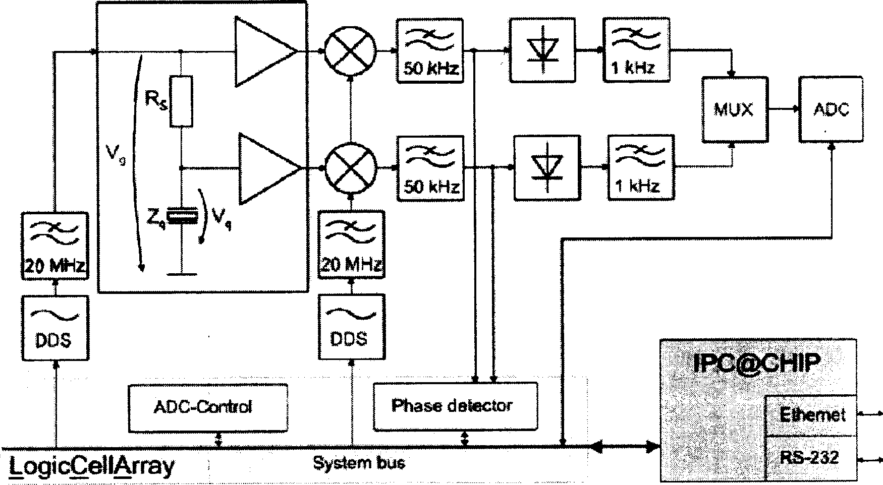
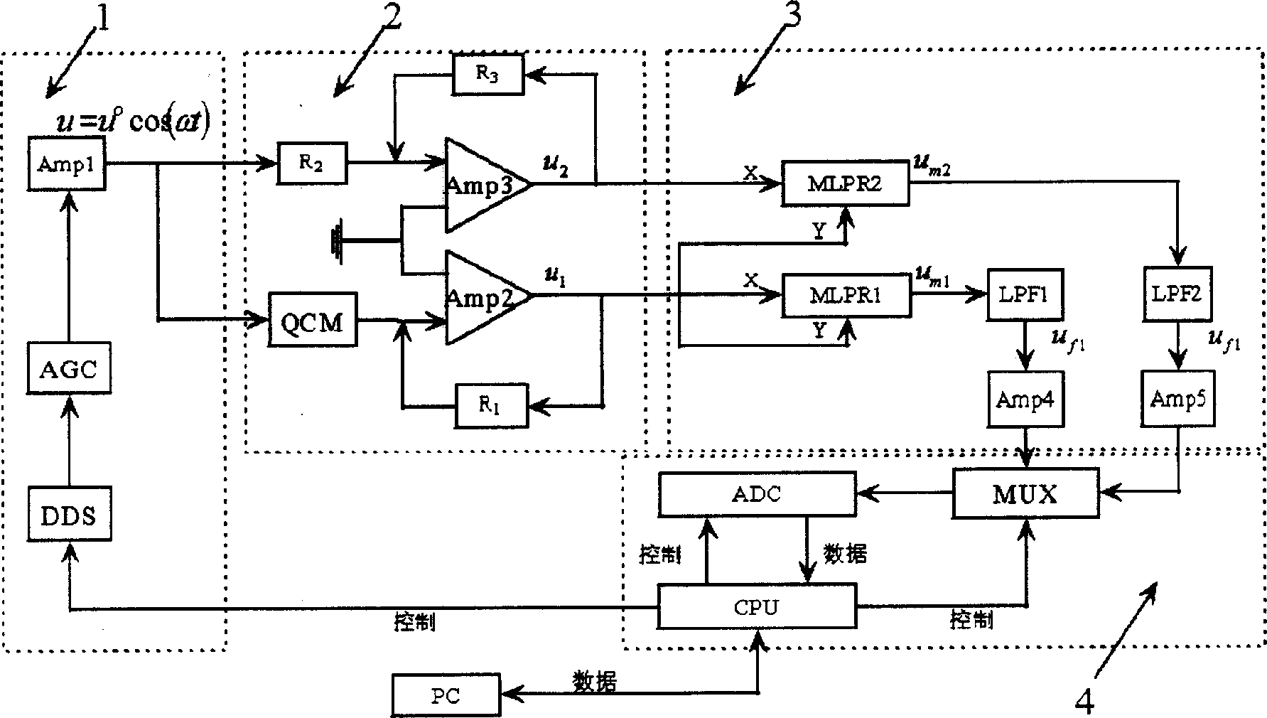
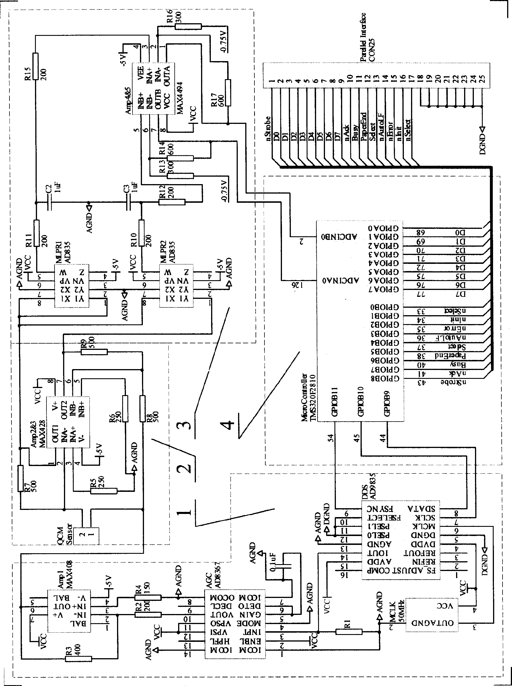
[0042] Below with the accompanying drawings ( figure 2 , 3 ) The present invention is described in detail: in a specific embodiment of the present invention, the fundamental frequency (Fundamental Frequency) of QCM is 5MHz. The DDS chip uses AD9835, and the automatic gain control is built by AD8367. AD8367 is a variable gain amplifier with integrated square-law detector (Square-Law Detector) on-chip. Using this chip can easily build an automatic gain control amplifier AGC. The multiplier uses the AD835. CPU adopts DSP chip TMS320F2810, because this DSP chip comes with 16-way 12-bit AD conversion circuit, so the multi-way switch and analog-to-digital converter in the schematic diagram are actually omitted in the embodiment. The communication between the resonant sensor drive and the signal collector and the PC is realized through the parallel port, and the selected parallel port work mode is PS / 2 mode. It has been verified that when the circuit of the embodiment works in m...


PUM


Abstract

This invention relates to a resonance sensor drive and signal collection device, which comprises the following parts: the sine signal generator circuit composed of DDS, AGC and Amp1; the sensor drive circuit composed of computation amplifier, sensor and reference resistance; the analog signal collection and process circuit composed of analog multiplier, low pass filter and level conversion computation amplifier; the digit signal collection and process and control circuit composed of multiple-path switch, A / D converter and central processor.

Description

technical field [0001] The invention relates to an electronic device capable of measuring impedance spectrum in real time, especially for driving and measuring a resonant sensor. It is designed for quartz microbalances (QCMs), but can also be used with other types of resonant sensors. Background technique [0002] Quartz microbalance is a resonant sensor composed of circular gold electrodes plated on the upper and lower surfaces of a circular AT-cut quartz plate. It has the advantages of simple structure, low cost, high sensitivity, real-time on-line detection, and small vibration loss in the liquid phase, etc., and has broad application prospects in the fields of biology, chemistry, environmental protection, and food. [0003] At present, there are mainly two methods for driving QCM vibration and collecting its output signal: (1) the method of oscillation circuit; (2) the method of frequency spectrum analysis. The basic principle of the oscillating circuit method is: conn...

Claims


Application Information

Patent Timeline
IPC IPC(8): G01R31/00
Inventor 常浩王琪民蒋海峰张培仁
Owner UNIV OF SCI & TECH OF CHINA
Why Eureka
Try Eureka