Zonal water injection contanst flow packer

A technology of constant flow plugging and layered water injection, which is applied in the direction of production fluid, wellbore/well components, earthwork drilling and production, etc., and can solve the problems of separate injection well commissioning and fishing, heavy testing workload, changes, increased deployment workload and Issues such as deployment difficulty

Inactive Publication Date: 2005-08-03
赵学增 +1
View PDF0 Cites 9 Cited by
  • Summary
  • Abstract
  • Description
  • Claims
  • Application Information

AI Technical Summary

Problems solved by technology

At present, ordinary downhole water injection plugs are generally used in domestic oilfields. Since the flow rate of the plugs changes with injection pressure or formation pressure fluctuations, it is difficult to control the water volume of each layer.
With the increasing num...

Method used


Image

  • Zonal water injection contanst flow packer
  • Zonal water injection contanst flow packer
  • Zonal water injection contanst flow packer

Examples


specific Embodiment approach 1

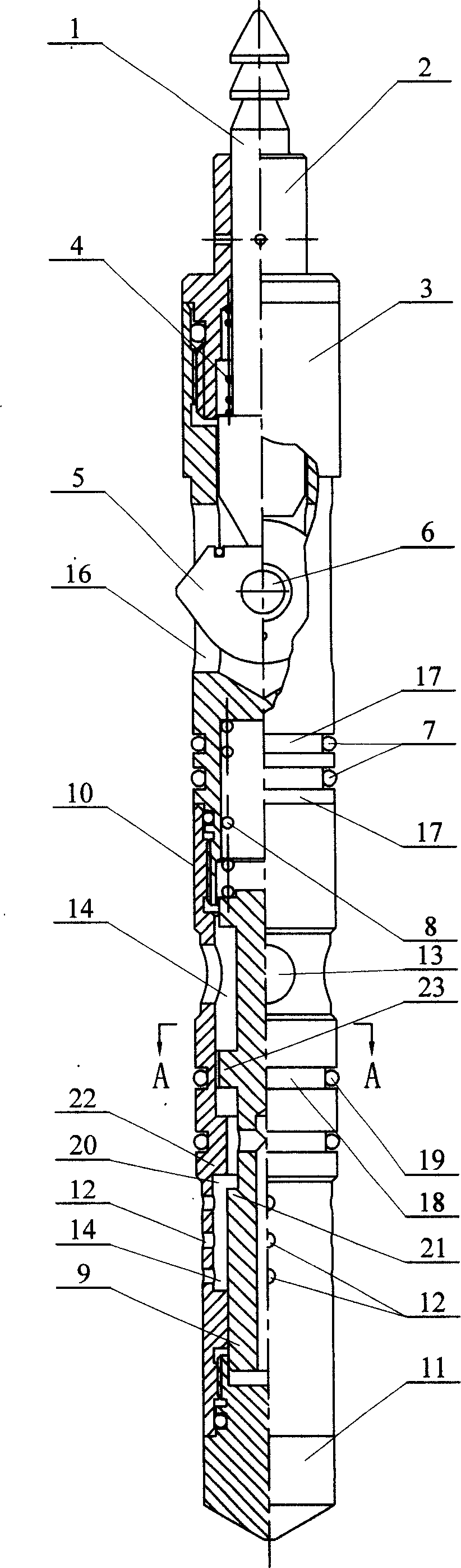
[0005] Specific implementation mode one: (see figure 1 , figure 2 ) This embodiment consists of a fishing rod 1, a pressure cap 2, a support seat 3, a spring 4, a cam 5, a small shaft 6, a first O-ring 7, a constant force spring 8, a sliding valve core 9, a valve sleeve 10, an inlet The pressure cap 11 and the second O-ring 19 are composed; the lower part of the fishing rod 1 is set in the pressure cap 2, the lower end of the pressure cap 2 is threadedly connected with the upper end of the support seat 3, and the lower part of the fishing rod 1 is connected with the lower end of the pressure cap 2. Spring 4 is arranged between, and small shaft 6 is located in support seat 3, and the inner end of cam 5 is arranged on the small shaft 6 in support seat 3, and the outer end of cam 5 is located at the opening groove 16 on support seat 3. Outside, the first O-ring seal 7 is arranged in the groove 17 of the lower part of the support seat 3, the lower end of the support seat 3 is th...

specific Embodiment approach 2

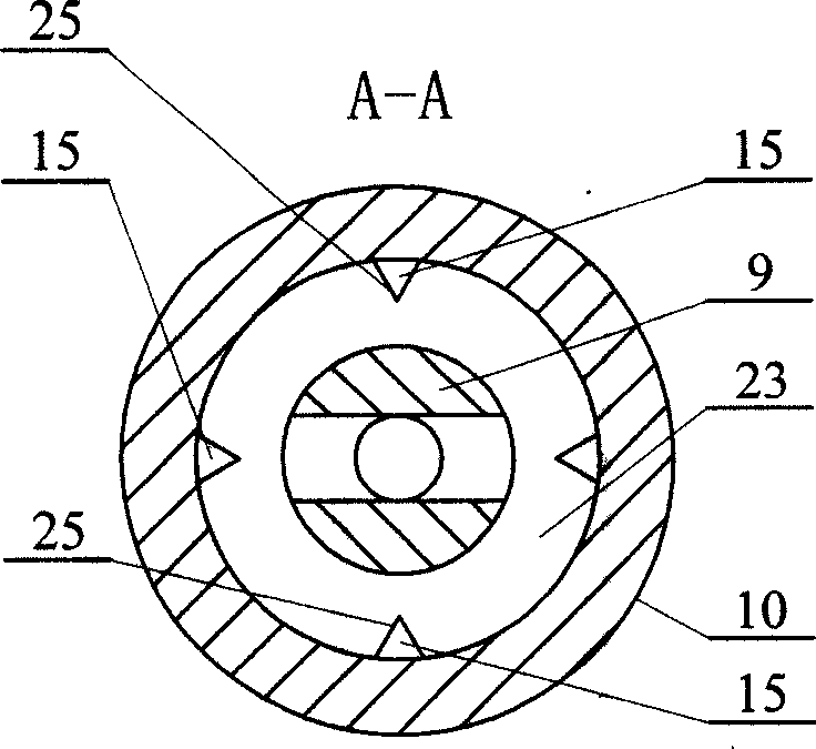
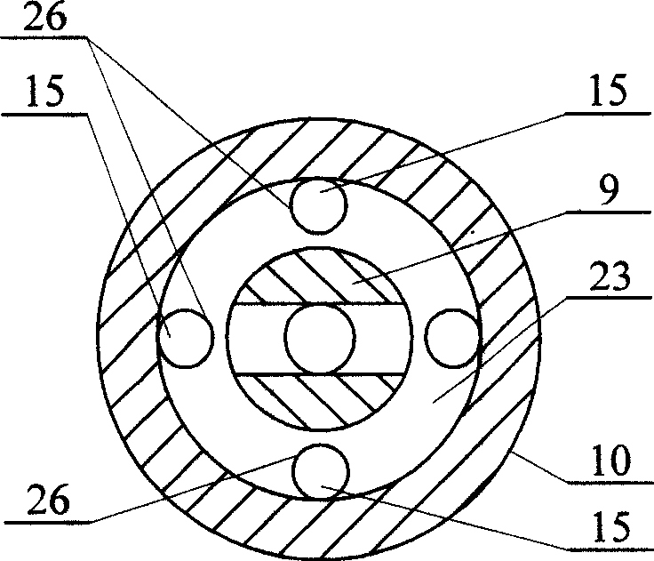
[0006] Specific implementation mode two: (see image 3 ) The difference between this embodiment and the first embodiment is that the section of the fixed orifice 15 is circular 26 . Other compositions and connections are the same as in the first embodiment.

specific Embodiment approach 3

[0007] Specific implementation mode three: (see Figure 4 ) The difference between this embodiment and the first embodiment is that the cross section of the fixed orifice 15 is a rectangle 27 . Other compositions and connections are the same as in the first embodiment.

[0008] Working principle: the present invention is equivalent to connecting the differential pressure reducing valve and the throttle valve in series and parallel to realize that when the water injection pressure difference fluctuates, the plug can also automatically adjust according to the pressure difference change and keep the water injection volume unchanged. Among them, the function of the fixed differential pressure reducing valve is to automatically change the flow area of ​​its variable orifice 20 according to the water injection pressure difference through the sliding spool 9 and the constant force spring 8, and then change its own partial pressure, and provide a fixed pressure to the throttle valve. ...


PUM


Abstract

The improved zonal water injection constant flow packer for oil field water injection well has sliding valve core, which is set inside the inner cavity of valve jacket, and has upper end connected to the lower end of supper seat with spring in between, shaft neck to form variable throttle hole with the flange in valve jacket cavity and water outlet hole in the valve jacket over its boss. The present invention has the beneficial effects of water injecting amount maintained constant, greatly shortened regulating time, lowered labor strength, and lowered water injection well regulating cost, excellent dynamic performance, raised water injection quality, certain automatic jamming preventing capacity, etc. and may be used directly in eccentric well zonal water injection system.

Description

Technical field: [0001] The invention relates to an improvement of a plug structure used for layered water injection of oil field water injection wells. Background technique: [0002] Water injection development is an important means for oilfields to achieve long-term stable and high production. It is the most widely used technology in maintaining formation pressure and improving oil recovery rate and recovery rate. Layered water injection is to solve the conflict between layers, It is an important means to achieve effective water injection, maintain formation energy, maintain long-term stable and high production of oilfields, and improve oil recovery. However, with the gradual deepening of the subdivision of water injection wells, the contradictions between water injection well layers are becoming more and more obvious. At present, ordinary downhole water injection plugs are generally used in domestic oil fields. Since the flow rate of the plugs changes with injection pres...

Claims


Application Information

Patent Timeline
IPC IPC(8): E21B43/20
Inventor 赵学增刘润发陈芳贾庆海刘长运王雅杰
Owner 赵学增
Why Eureka
Try Eureka