Deep cold loop heat tube

A loop heat pipe, cryogenic technology, applied in indirect heat exchangers, lighting and heating equipment, etc., can solve problems such as difficulty in starting the cryogenic loop heat pipe, and achieve the effect of stable working performance and large heat transfer limit.

Inactive Publication Date: 2005-08-03
TECHNICAL INST OF PHYSICS & CHEMISTRY - CHINESE ACAD OF SCI
View PDF0 Cites 20 Cited by
  • Summary
  • Abstract
  • Description
  • Claims
  • Application Information

AI Technical Summary

Problems solved by technology

[0007] In order to solve the problem of difficult startup of the cryogenic circuit heat pipe and increase

Method used


Image

  • Deep cold loop heat tube
  • Deep cold loop heat tube
  • Deep cold loop heat tube

Examples


Embodiment Construction

[0026] The present invention will be further described below in conjunction with the drawings and embodiments:

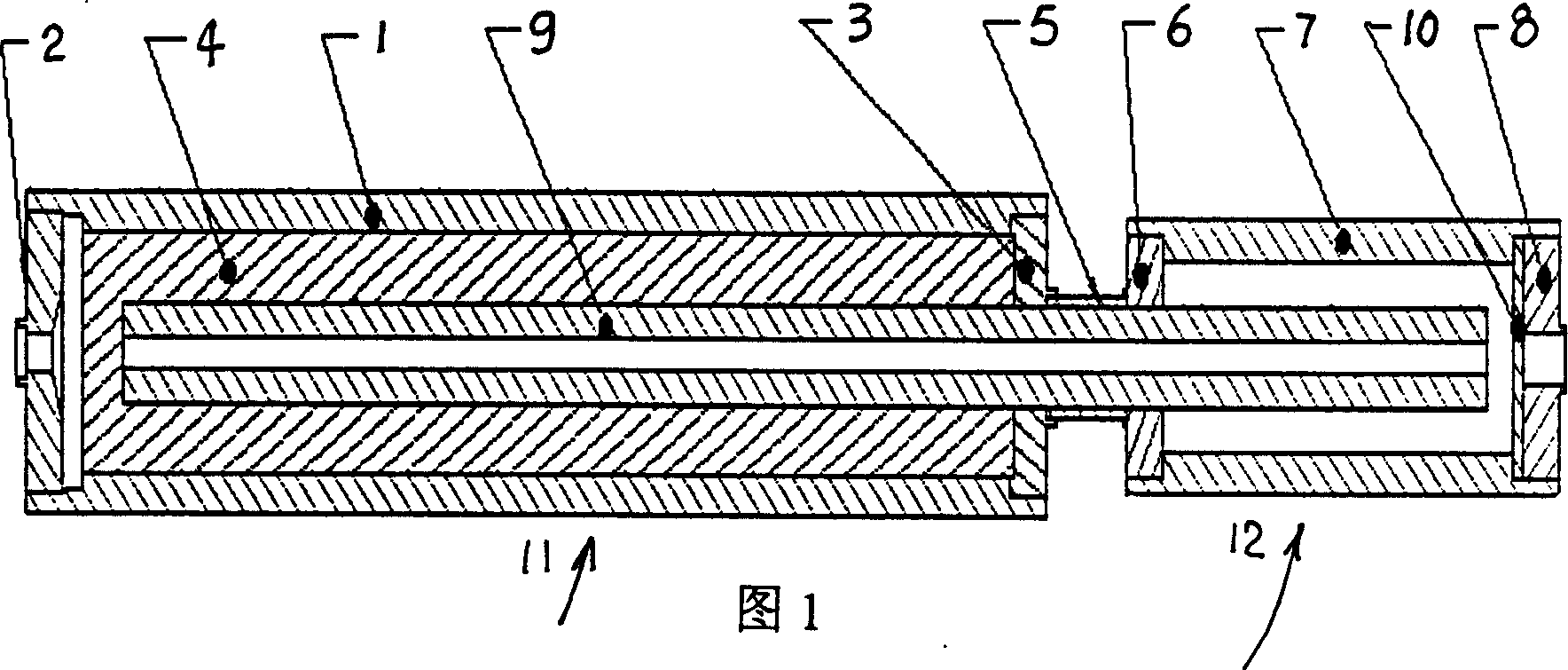
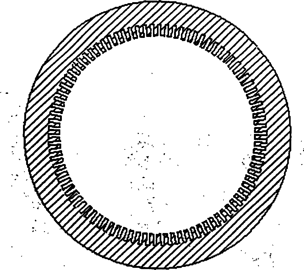
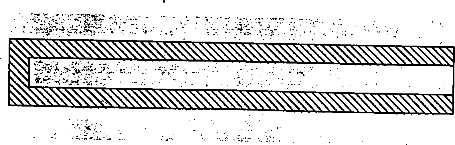
[0027] Figure 1 is a schematic diagram of the structure of the present invention; figure 2 A schematic cross-sectional view of the main evaporator shell 1; image 3 It is a schematic structural diagram of the cylindrical main liquid wick 4; it can be seen from the figure that the cryogenic loop heat pipe provided by the present invention includes:

[0028] A main evaporator 11;

[0029] A liquid reservoir 12; the main evaporator 11 and the liquid reservoir 12 are connected in series by a connecting pipe 5 into one body;

[0030]The main evaporator 11 includes a main evaporator tube shell 1, a left end cover of the main evaporator 2, a right end cover of the main evaporator 3, and a main wick 4, and the main evaporator tube shell 1 has a shaft cut on the surface of the inner hole. The hollow stainless steel tube facing the channel is coaxially placed in the cylindrical m...


PUM


Abstract

The deep cooling loop heat pipe includes main evaporator and liquid chamber connected serially via connecting pipe. The main evaporator has casing of stainless steel pipe with axial grooves in the inside surface and main tubular liquid absorbing core of sintered stainless steel powder. The liquid chamber has stainless steel wire screen filled between the right end cap and the casing. There are also capillary connecting part, which has central inside hole, is set inside the hole of the main liquid absorbing core and extends via the connecting pipe to the liquid chamber, and annular coarse stainless steel wire sheet filled between the capillary connecting part and the liquid chamber casing. The present invention can avoid reverse flow of the work medium to ensure the successful starting of deep cooling loop heat pipe, and can raised the heat transferring limit of deep cooling loop heat pipe for stable operation performance.

Description

Technical field [0001] The invention belongs to a loop heat pipe in the technical field of refrigeration and low temperature, and particularly relates to a deep cold loop heat pipe used for improving the integration relationship between a low temperature refrigerator and a cooled device in a low temperature integrated system for space. Background technique [0002] With the development and wide application of cryogenic refrigerator technology, it is becoming more and more obvious to consider how to effectively transmit cold energy over long distances. Therefore, the cryogenic refrigerator and the device to be cooled should be integrated as a system rather than a device, which can enhance the refrigeration capacity of the refrigeration system. [0003] At present, the common method for connecting the refrigerator and the cooled device is to use copper rods for heat conduction. The disadvantage is that when the heat transfer distance becomes longer, the temperature difference betwe...

Claims


Application Information

Patent Timeline
IPC IPC(8): F28D15/02
CPCF28D15/0266
Inventor 莫青蔡京辉梁惊涛
Owner TECHNICAL INST OF PHYSICS & CHEMISTRY - CHINESE ACAD OF SCI
Why Eureka
Try Eureka