Electric spark machining liquid storage case device for treatment fluid containing addition agent

An additive, electric spark technology, applied in the field of processing and circulation devices, storage, can solve the problem of low working life of the working fluid

Inactive Publication Date: 2005-08-17
HARBIN INST OF TECH
View PDF0 Cites 5 Cited by
  • Summary
  • Abstract
  • Description
  • Claims
  • Application Information

AI Technical Summary

Problems solved by technology

[0003] In order to solve the problem of low working life of the working fluid in the existing electric discharge machining, an electric discha...

Method used


Image

  • Electric spark machining liquid storage case device for treatment fluid containing addition agent

Examples


specific Embodiment approach 1

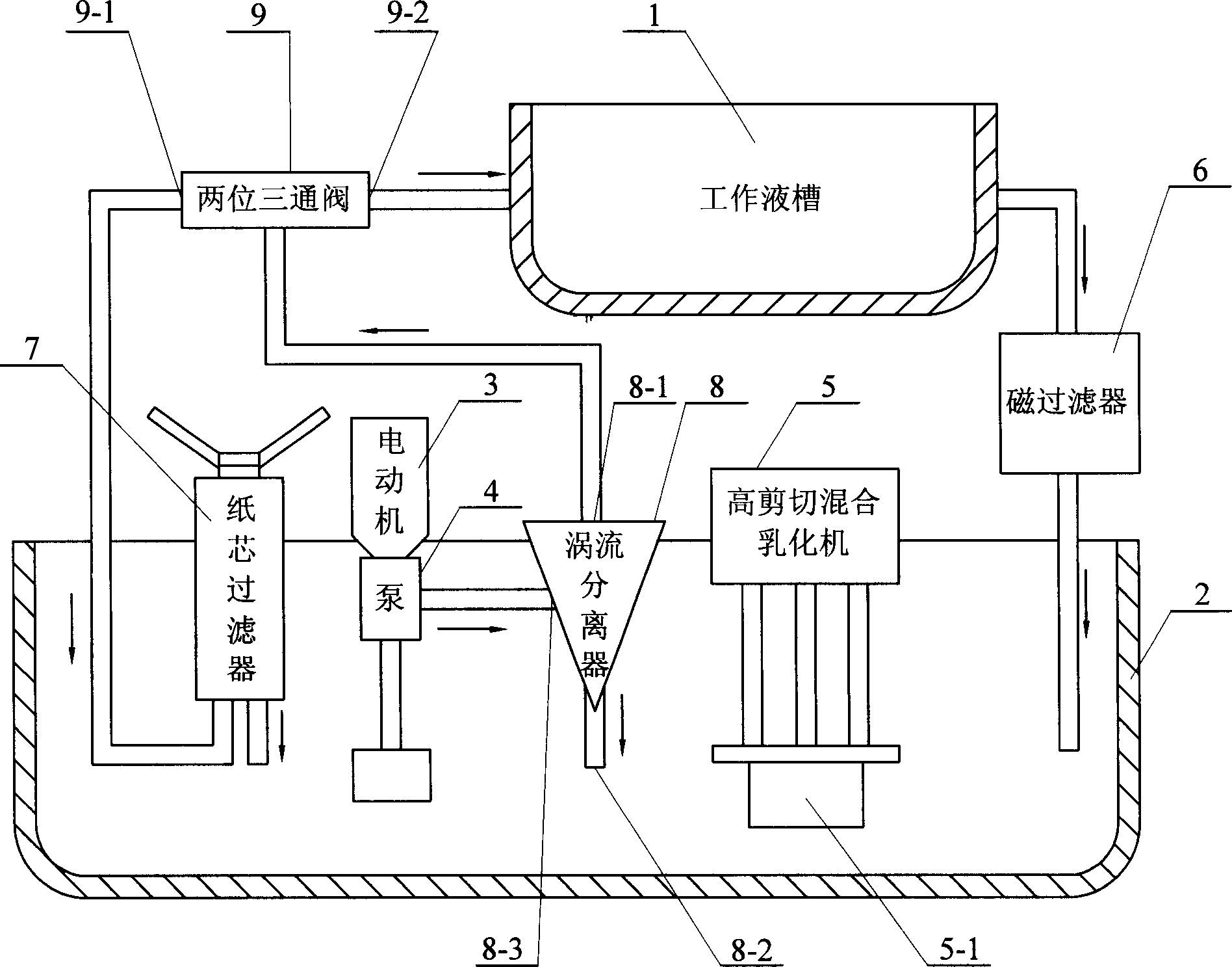
[0005] Specific implementation mode one: the following combination figure 1 This embodiment will be specifically described. It consists of a working liquid tank 1, a liquid storage tank 2, a vortex separator assembly, a high-shear mixing emulsifier 5, a magnetic filter 6, a two-position three-way valve 9, and a paper core filter 7. The eddy current separator assembly consists of a pump 4. Composed of motor 3 and eddy current separator 8, the liquid inlet of magnetic filter 6 is connected to the liquid outlet of working fluid tank 1, and the liquid outlet of magnetic filter 6 is connected to liquid storage tank 2, high shear mixing and emulsification The stirring blade 5-1 of the machine 5 extends into the liquid storage tank 2, the motor 3 provides power to the pump 4, the inlet of the pump 4 extends into the liquid storage tank 2, and the outlet of the pump 4 communicates with the inlet 8 of the vortex separator 8 -3, the lower outlet 8-2 of the vortex separator 8 extends in...


PUM


Abstract

The present invention is electric spark machining liquid storing device with additive in the work liquid, and relates to the work liquid storing, processing and circulating device. The present invention includes work liquid trough, liquid storing trough, eddy current separator assembly, high shearing mixed liquefying machine, magnetic filter, two-position three-way valve and paper element filter. The eddy current separator assembly consists of pump, motor and eddy current separator. Owing to the filtering off of the machined electric corrosion slag and the stirring and filtering treatment of the conducting powder, the present invention has the work life of the work liquid about one time prolonged.

Description

Technical field: [0001] The invention relates to a storage, treatment and circulation device for working fluid in electric discharge machining. Background technique: [0002] The traditional EDM working fluid is circulated in this way: the working fluid is pumped out from the storage tank through the pump and sent to the electrode processing working fluid tank to participate in the machining of the workpiece by the electrode, and the processing working fluid in the working fluid tank is performing the above process After the process, it enters the filter from the lower part of the liquid tank, filters and removes waste impurities generated by processing, and then returns to the liquid storage tank to prepare for the next cycle. At present, in the field of electric discharge machining, a method of adding semiconductor powder to the original machining working fluid is adopted. This method has the advantages of high processing efficiency and good quality, but due to the coexist...

Claims


Application Information

Patent Timeline
IPC IPC(8): B23H1/10B23H3/10B23H5/14B23H7/36
Inventor 索来春
Owner HARBIN INST OF TECH
Why Eureka
Try Eureka