Permanent magnet biased axial hybrid magnetic bearing

An axial hybrid, magnetic bearing technology, applied in the directions of shafts and bearings, bearings, mechanical equipment, etc., can solve the problems of reducing the critical speed of the suspended rotor, increasing the axial length of the magnetic bearing, and increasing the difficulty of the control system, so as to improve the critical speed. , the effect of reducing power consumption and increasing the application range

Active Publication Date: 2013-01-30
江阴智产汇知识产权运营有限公司
View PDF8 Cites 19 Cited by
  • Summary
  • Abstract
  • Description
  • Claims
  • Application Information

AI Technical Summary

Problems solved by technology

[0003] Chinese Patent Publication No. CN101038011, named "three-degree-of-freedom AC hybrid magnetic bearing", combines radial two-degree-of-freedom and axial single-degree-of-freedom, and has the advantages of high integration and small volume, but its defects are: radial There is a coupling between the force and the axial force, which increases the difficulty of the control system
Chinese Patent Publication No. CN101025198, titled "A Permanent Magnet Bias Axial Hybrid Magnetic Bearing" is an axial single-degree-of-freedom magnetic suspension bearing, which only uses a radially magnetized circular permanent magnet. Simple, the axial control windings are located on both sides of the radial stator, which increases the axial length of the magnetic bearing and reduces the critical speed of the suspended rotor

Method used


Image

  • Permanent magnet biased axial hybrid magnetic bearing
  • Permanent magnet biased axial hybrid magnetic bearing
  • Permanent magnet biased axial hybrid magnetic bearing

Examples


Embodiment Construction

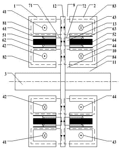
[0017] Such as figure 1 As shown, the present invention includes a first stator disc 1, a second stator disc 2, a suction disc 12, a rotating shaft 3, two annular permanent magnets, four magnetic isolation rings, four sets of control coils, and two outer rings -Shaped coil slots, two inner circular ring-shaped coil slots, two circular ring-shaped permanent magnet slots and four circular ring-shaped magnetic isolation ring slots.

[0018] Among them, the first stator disc 1, the second stator disc 2 and the suction disc 12 are all coaxial with the rotating shaft 3 and sleeved on the rotating shaft 3. The first stator disc 1 and the second stator disc 2 have the same structure and are located respectively The suction cup 12 is arranged on both sides in the axial direction and symmetrically with respect to the suction cup 12. The outer diameters of the first stator disc 1, the second stator disc 2 and the suction disc 12 are all equal.

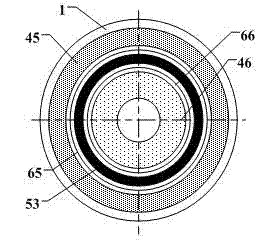
[0019] See figure 1 with figure 2 , On the ...


PUM


Abstract

The present invention discloses a permanent magnet biased axial hybrid magnetic bearing, which comprises two stator discs having the same structure, wherein the two stator discs are arranged relative to a suction disc in an axially symmetric manner, the disc surface of every stator disc is provided with an outer annular coil groove, two annular magnetic isolation ring grooves, an annular permanent magnet groove and an inner annular coil groove along a radial direction from outside to inside, the two annular magnetic isolation ring grooves are respectively positioned on both radial sides of the annular permanent magnet groove, control coils are arranged inside every inner annular coil groove and every outer annular coil groove, a magnetic isolation ring is intercalated inside each annular magnetic isolation ring groove, an annular permanent magnet is pressed into each annular permanent magnet groove, and every annular permanent magnet is radially magnetized. According to the present invention, a static bias magnetic field is generated by the permanent magnet material so as to reduce magnetic bearing volume, lower power amplifier power consumption, and improve carrying capacity of the magnetic bearing; and the annular permanent magnet is embedded in the middle of the stator disc so as to ensure suction disc stiffness and upper-lower symmetry and left-right equality of the provided bias magnetic field.

Description

technical field [0001] The invention relates to a non-mechanical contact magnetic bearing, in particular to a permanent magnet bias axial hybrid magnetic bearing, which is suitable for mechanical equipment such as five-degree-of-freedom magnetic bearing systems, axial positioning of bearingless motors, and high-speed flywheel energy storage systems. Axial non-contact suspension support of rotating parts. Background technique [0002] Since the rapid development of magnetic bearing technology in the 1970s, since the bias magnetic field of the hybrid magnetic suspension bearing is generated by the permanent magnetic material, the electromagnetic coil only generates the control magnetic field, which has the advantages of low power consumption and small size, and has become a research hotspot. . The technology of radial hybrid magnetic bearings has become mature, but the technology of single-degree-of-freedom axial hybrid magnetic bearings is still rare, especially the design o...

Claims


Application Information

Patent Timeline
Patent Type & Authority Applications(China)
IPC IPC(8): F16C32/04
Inventor 周超朱熀秋魏杰张维煜
Owner 江阴智产汇知识产权运营有限公司
Why Eureka
Try Eureka