Rotor of hydraulic pulper

A hydraulic pulper and rotor technology, which is applied in the field of papermaking machinery, can solve the problems of bulky size, large installation area, and heavy weight, and achieve the effects of improving dissociation efficiency, benefiting circulation, and saving materials

Inactive Publication Date: 2005-08-24
李风宁
View PDF0 Cites 3 Cited by
  • Summary
  • Abstract
  • Description
  • Claims
  • Application Information

AI Technical Summary

Problems solved by technology

And because in the initial stage of waste paper shredding, the volume and weight of each shredded paper are very large, when they directly collide with the vertical knife on the inner wall of the shell, some fibers in the shredded paper will be cut off and non-fibrous. Impurities are destroyed
Moreover, the drum pulper has a large volume and occupies a large area for installation; secondly, it has a large weight, and the rolling body itself consumes a lot of energy; thirdly, the cost of various drum pulpers is too high

Method used


Image

  • Rotor of hydraulic pulper
  • Rotor of hydraulic pulper
  • Rotor of hydraulic pulper

Examples


Embodiment 1

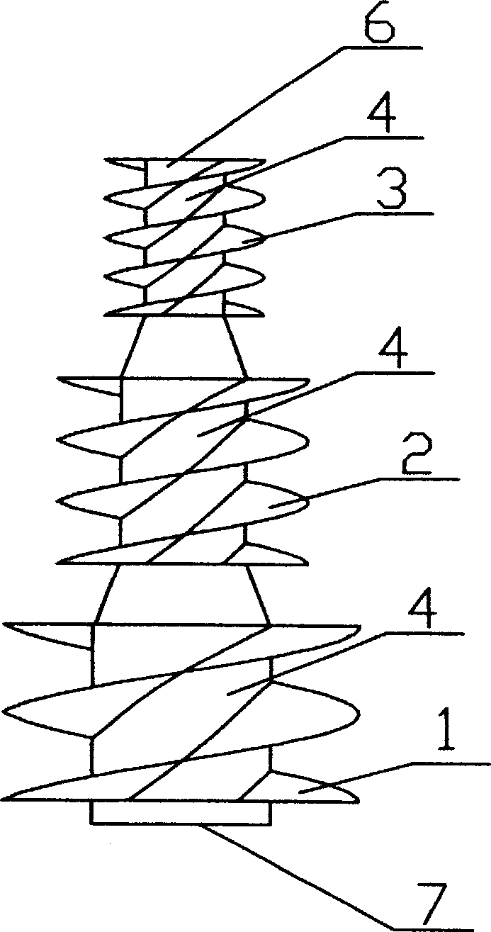
[0013] Embodiment one: if figure 1 As shown, a hydropulper rotor includes a rotor central shaft 4, screw blades 1, 2, and 3 fixed on the central shaft 4, the rotor central shaft 4 is a stepped shaft, free from the central shaft 4 The shaft diameters of the stepped shafts from the end 6 to the driving end 7 increase sequentially, the shaft sections of the stepped shafts with different shaft diameters transition smoothly through conical surfaces, and the shaft sections of the stepped shafts with different shaft diameters are respectively provided with spiral The blades 1, 2, 3, the pitches between the helical blades 1, 2, 3 respectively provided on the shaft sections with different shaft diameters are different.

[0014] The outer edges of the helical blades 1, 2, and 3 respectively provided on the shaft sections with different shaft diameters are distributed in a cylindrical surface. This distribution can be that the edges of the helical blades 1, 2, and 3 are distributed in a...

Embodiment 2

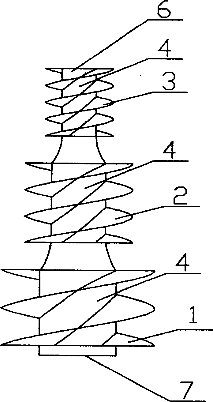
[0016] Embodiment 2: The structural form is basically the same as that of Embodiment 1, except that the shaft sections of the stepped shafts with different shaft diameters transition smoothly through the streamline surface, so that the circulation of the slurry is smooth and unimpeded.

Embodiment 3

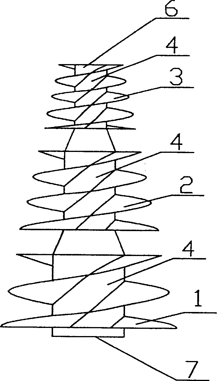
[0017] Embodiment 3: The structural form is basically the same as Embodiment 1 and Embodiment 2, the difference is that the outer edges of the spiral blades 1, 2, 3 respectively provided on the shaft sections with different shaft diameters are distributed in the In a conical surface, the distribution may be that the edges of the helical blades 1, 2, and 3 are distributed in a common conical surface, and the edges of the helical blades 1, 2, and 3 may also be distributed in their respective conical surfaces.


PUM


Abstract

The invention discloses a rotator of hydraulic pulp kneader, including several groups of spiral leaf with different distance on the central axial and the thrust to brei are different, so that vorticity circulation and local vorticity circulation are formed, the times of collision is increased and the waste paper is scattered to be the single fiber. The invention has simple structure, convenient procession, high work effiency and energy saving.

Description

technical field [0001] The invention belongs to the field of papermaking machinery, and in particular relates to a rotor of a hydraulic pulper. Background technique [0002] There are three principles for the shredding of various waste papers: one is to completely eliminate fiber bundles; the other is not to cut or cut fibers as little as possible; the third is not to destroy or damage various non-fibrous impurities as little as possible. [0003] The bottom of the rotor of various existing hydropulpers is equipped with a bottom knife, which has strong mechanical friction with the bottom of the shell of the hydropulper. This strong mechanical friction will cause the fibers to be cut off at one time, and will Destroying various non-fibrous impurities will cause a substantial increase in power consumption. In order to solve the above problems, Ahlstrom Company of Finland has developed a drum pulper, the basic principle of which is attached Figure 4 As shown, this kind of pul...

Claims


Application Information

Patent Timeline
Patent Type & Authority Applications(China)
IPC IPC(8): D21B1/32D21B1/34
CPCY02W30/64
Inventor 李风宁
Owner 李风宁
Why Eureka
Try Eureka