Low-power electronic current mutual inductor

A current transformer and electronic technology, applied in the field of transformers, can solve the problems of easy saturation of the coil, dead zone of the power supply, low emission power of the laser source, etc., and achieve the effects of simplifying the production process, expanding the measurement range, and large measurement range

Active Publication Date: 2005-08-24
传奇电气(沈阳)有限公司
View PDF2 Cites 16 Cited by
  • Summary
  • Abstract
  • Description
  • Claims
  • Application Information

AI Technical Summary

Problems solved by technology

The main problem of this technology lies in the power supply of the electronic circuit on the primary high-voltage side and the service life during long-term operation. At present, the main power supply methods include laser source power supply and busbar coil power supply (that is, using a small current transformer coil from the primary high-voltage side get power supply)
The main problem of laser source power supply is that the emission power of the laser source is low, the power provided is limited, and the price is high and the service life is short, which makes the manufacturing cost of the hybrid photoelectric current transformer very high, and it is difficult to maintain on site after operation.
However, when the coil of the bus-type current transformer is used for power supply, there is a problem of "dead zone" of the power supply that the coil is easily saturated when passing a small current once, and the coil is easily saturated when passing a large current, which affects the stable operation of the electronic circuit.
Therefore, although some products of this hybrid photoelectric current transformer are connected to the grid, it is still difficult to achieve large-scale production and application.

Method used


Image

  • Low-power electronic current mutual inductor
  • Low-power electronic current mutual inductor
  • Low-power electronic current mutual inductor

Examples


Embodiment Construction

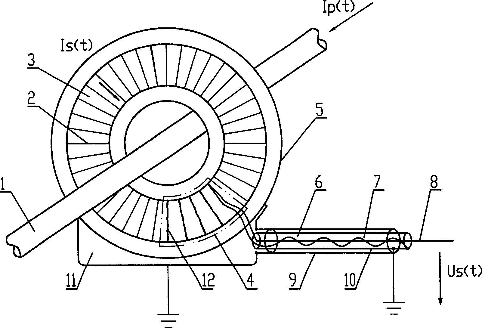
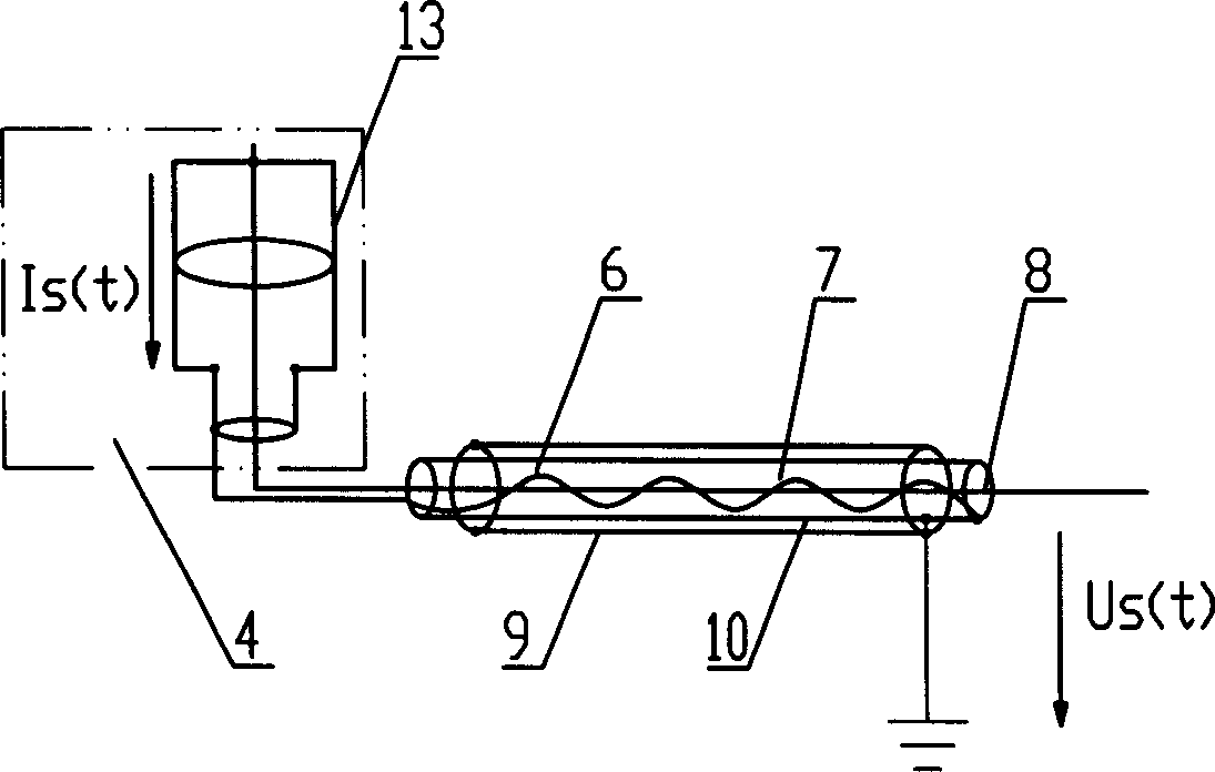
[0023] Such as figure 1 , figure 2 As shown, the present invention is a passive device, including: a primary winding 1, a secondary winding 2, a magnetic core 3, a secondary shunt resistor 4, a shielding shell 5, a double shielded twisted pair 6 and a base 11, and the primary winding 1 runs through Through the center of the magnetic core 3, the shielding shell 5 and the base 11 form a whole, the secondary copper wire is evenly wound on the annular magnetic core, and a secondary shunt resistor 4 is connected to the end of the secondary copper wire, and the secondary shunt resistor is also Evenly wound on the annular magnetic core and the secondary copper wire to form the secondary winding 2, the entire secondary winding is placed in a shielded shell 5 that will not produce short-circuit turns, and the secondary low-power voltage signal is provided by a double-shielded twisted pair 6 output.

[0024]The magnetic core 3 is made of a magnetic soft alloy strip, the shape of the ...


PUM


Abstract

This invention relates to a low-power electronic current transformer, and is the equipment without power source. It includes primary winding, secondary winding, magnet core, secondary shunt resistance, screen cover, double-screen multiple twin and base frame. The primary winding passes through the center of the magnet core, the secondary brown lead circles around the magnet core evenly, the screen cover and the base frame integrate together, a secondary shunt resistance connects with the end of the secondary brown lead, and the secondary shunt resistance also circles evenly around the secondary winding composed of magnet core and the secondary brown lead, the whole secondary winding is put in the screen cover, the secondary low-power voltage is output by the double-screen multiple twin. The secondary output of this invention is the low-power voltage signal that has linearity proportion relation with the primary current; a transformer winding can meet all kinds of demands of measurement and protection at the same time; the measuring distance is far, the precision is high; it does not have the secondary loop problem, it is open-circuit and short-circuit, and the weight is light, the cost of materials is low and the magnetic compatibility is strong.

Description

technical field [0001] The invention relates to a transformer used in the technical field of electric system current measurement and relay protection, in particular to a low-power electronic current transformer. Background technique [0002] With the widespread application of relay protection and measurement systems based on microcomputer technology, the power requirements for input signals are greatly reduced. In practical applications, since the energy level provided by these signals is far beyond the range that microelectronic components can withstand, they must be further converted into low-power analog voltage signals through current / voltage transmitters before they can be input to relays Digital signal sampling is carried out in the analog / digital conversion module of the measuring system. In the current power transmission and transformation system, the acquisition of the primary high-voltage current signal is mainly realized through the traditional electromagnetic cu...

Claims


Application Information

Patent Timeline
Patent Type & Authority Applications(China)
IPC IPC(8): G01R15/00H01F38/28
Inventor 鲁特哈尔德・明克讷约阿希姆・施密特
Owner 传奇电气(沈阳)有限公司
Why Eureka
Try Eureka