Liquid crystal display device with backlight unit using microlens array and fabricating method of microlens array

A technology of microlens array and microlens, which is applied in the direction of lens, instrument, optics, etc., can solve the problems of reducing viewing angle, brightness, chromatic aberration, etc.

Inactive Publication Date: 2005-08-31
LG ELECTRONICS INC +1
View PDF0 Cites 15 Cited by
  • Summary
  • Abstract
  • Description
  • Claims
  • Application Information

AI Technical Summary

Problems solved by technology

Chromatic aberration occurs through increased phase d

Method used


Image

  • Liquid crystal display device with backlight unit using microlens array and fabricating method of microlens array
  • Liquid crystal display device with backlight unit using microlens array and fabricating method of microlens array
  • Liquid crystal display device with backlight unit using microlens array and fabricating method of microlens array

Examples


Embodiment Construction

[0034] Preferred embodiments of the invention will now be described in detail, examples of which are illustrated in the accompanying drawings.

[0035] Hereinafter, the backlight module LCD device using the microlens array and the manufacturing method of the microlens array will be described in more detail.

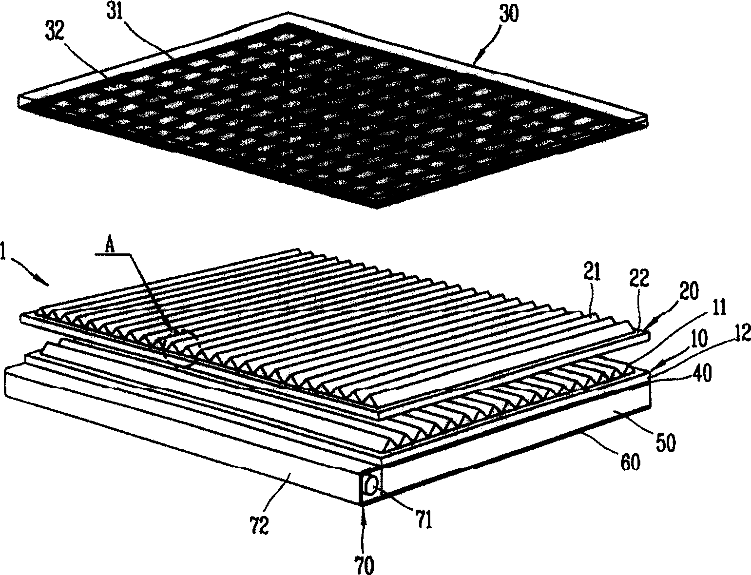
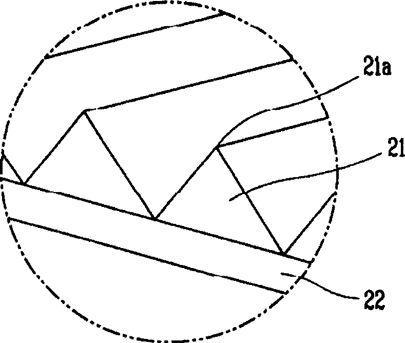
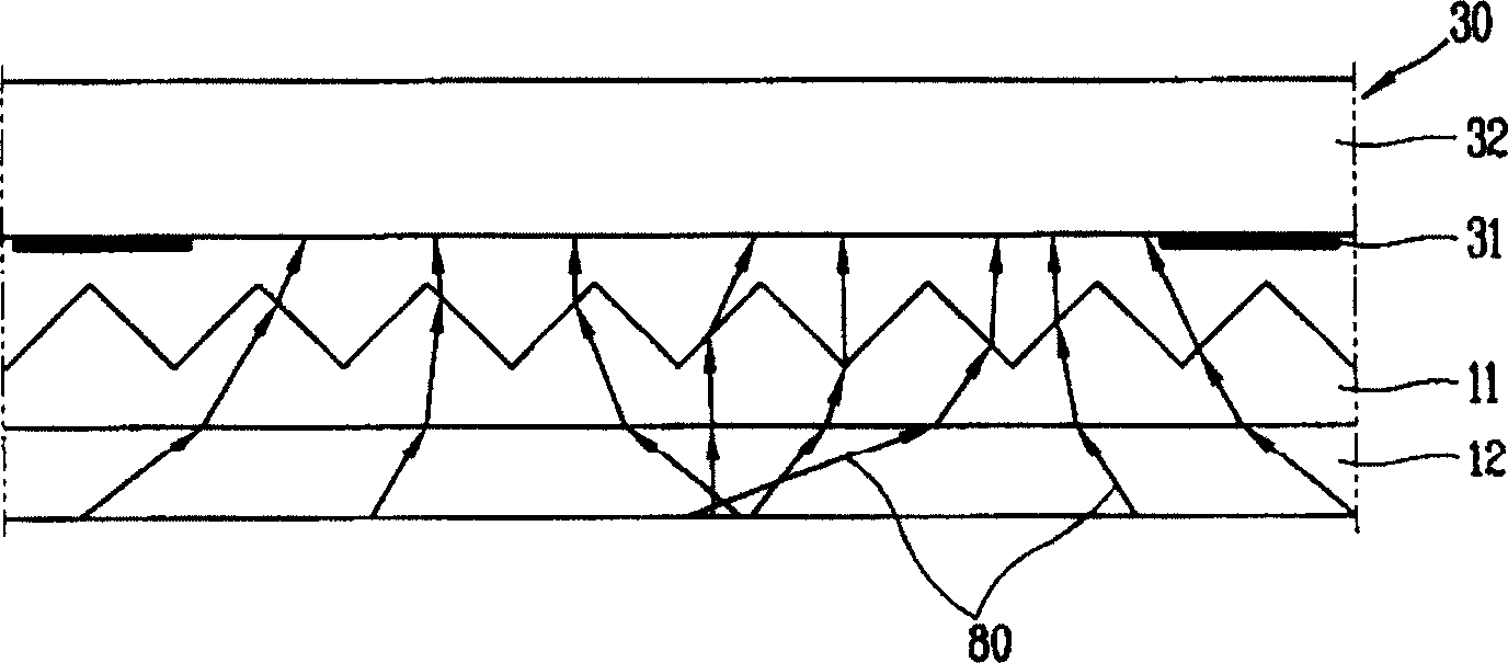
[0036] Figure 4 It is an exploded perspective view of an LCD device with a backlight module using a microlens array according to a specific embodiment of the present invention, Figure 5 for along Figure 4 A side view of the microlens array of the V-V line, Figure 6 for along Figure 4 A side view of the microlens array on line VI-VI, Figure 7 to represent Figure 4 A plan view of the arrangement state of the liquid crystal panel and the microlens array, Figure 8 It is a conceptual view showing a light collecting function of a backlight panel module using a microlens array according to the present invention.

[0037] As shown in the figure, according to an emb...


PUM


Abstract

An LCD device comprises: a light irradiating portion; a microlens array having a plurality of microlenses for collecting light emitted from the light irradiating portion; and a liquid crystal panel having a plurality of unit pixels, each unit pixel matching with the plural microlenses, for displaying an image by passing light that has been collected into the microlens array through each unit pixel. According to this, a color degradation is reduced, a viewing angle is increased, a fabrication cost is reduced, and fabrication time is shortened.

Description

technical field [0001] The invention relates to a liquid crystal display device with a backlight panel module using a microlens array and a manufacturing method of the microlens array. Background technique [0002] Recently, there has been an increasing demand for LCD devices that can realize a large screen and high image quality. However, it is difficult to make an LCD device using a conventional cathode ray tube (CRT) small and realize a screen larger than a certain size. Therefore, a flat panel display (FPD) capable of being made small and realizing a large screen and high image quality has attracted public attention, and research on the FPD has been actively conducted. [0003] LCD is one of the most talked about flat panel displays. [0004] The LCD device utilizes electro-optic properties of liquid crystals in an intermediate state between liquid and solid states as a display device. The LCD device utilizes the principle that the arrangement of organic molecules of ...

Claims


Application Information

Patent Timeline
IPC IPC(8): F21V8/00F21Y103/00G02B3/00G02F1/1335G02F1/13357
CPCG02F1/133526G02B6/005G02F2001/133607G02F1/133607G02F1/1335
Inventor 李泳柱李根雨朴纪垣成东默
Owner LG ELECTRONICS INC
Why Eureka
Try Eureka